English Manual
Page 5
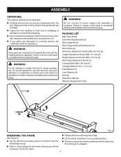
... (4) Flat Washers (4) Lock Washers (4) Nuts (4) Operator's Manual Warranty Registration Card LEG LOCKING PIN Fig. 2 preparing the stand n Repeat with the n Check to power supply until the missing parts are missing do so could result in accidental starting and possible serious personal injury. n Lay the... sure that leg up until you have folded legs on the floor with the remaining three legs. n Lift the stand and place it in . PACKING LIST Miter Saw Stand Saw Mounting Brackets (2) Work Supports (2) Work Support Mounting Brackets (2) Work Stops (2) Extension Adjustment Knobs (M8 x ...
... (4) Flat Washers (4) Lock Washers (4) Nuts (4) Operator's Manual Warranty Registration Card LEG LOCKING PIN Fig. 2 preparing the stand n Repeat with the n Check to power supply until the missing parts are missing do so could result in accidental starting and possible serious personal injury. n Lay the... sure that leg up until you have folded legs on the floor with the remaining three legs. n Lift the stand and place it in . PACKING LIST Miter Saw Stand Saw Mounting Brackets (2) Work Supports (2) Work Support Mounting Brackets (2) Work Stops (2) Extension Adjustment Knobs (M8 x ...
English Manual
Page 8
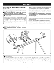
... make sure the curved front edge of the mounting brackets are designed to fit snugly over the stand rails. With the locking levers in the lowered (locked) position, you , lift the front part of the assembly to remove the saw and bracket assembly from the front rail of the... 8 To remove saw from the rear rail of the saw and mounting bracket assembly. n Lift away from stand: n Raise the locking levers to disengage. ASSEMBLY MOUNTING THE MITER SAW TO THE STAND See Figures 8 - 9. n Lift the saw and bracket assembly immediately and tighten the bracket adjustment screw as...
... make sure the curved front edge of the mounting brackets are designed to fit snugly over the stand rails. With the locking levers in the lowered (locked) position, you , lift the front part of the assembly to remove the saw and bracket assembly from the front rail of the... 8 To remove saw from the rear rail of the saw and mounting bracket assembly. n Lift away from stand: n Raise the locking levers to disengage. ASSEMBLY MOUNTING THE MITER SAW TO THE STAND See Figures 8 - 9. n Lift the saw and bracket assembly immediately and tighten the bracket adjustment screw as...
English Manual
Page 12
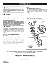
... to be damaged by their use only identical replacement parts. If the saw and bracket assembly can damage,...serious personal injury. GENERAL MAINTENANCE Avoid using solvents when cleaning plastic parts. n Turn the screw with the second mounting bracket. n... safety goggles or safety glasses with plastic parts. n Install the bracket on the miter stand rails and lower the locking lever to ...If the saw and bracket assembly will not fit over the stand rails. If operation is achieved, wrench tighten the nut to...(part no. To adjust: n Use a wrench to remove dirt, dust,...
... to be damaged by their use only identical replacement parts. If the saw and bracket assembly can damage,...serious personal injury. GENERAL MAINTENANCE Avoid using solvents when cleaning plastic parts. n Turn the screw with the second mounting bracket. n... safety goggles or safety glasses with plastic parts. n Install the bracket on the miter stand rails and lower the locking lever to ...If the saw and bracket assembly will not fit over the stand rails. If operation is achieved, wrench tighten the nut to...(part no. To adjust: n Use a wrench to remove dirt, dust,...
Repair Sheet
Page 3
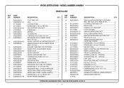
... WASHER (5/16 X D16 X 1.2t 4 * CARRIAGE BOLT (5/16-18 X 2 in 4 WARNING LABEL 2 OPERATOR'S MANUAL (9000225330501) REPAIR SHEET (REV:02) * STANDARD HARDWARE ITEM - SPECIAL 2 SCREW B (PAN HD. - RYOBI MITER STAND - MODEL NUMBER A18MS01 PARTS LIST KEY NO. 1 2 3 4 5 6 7 8 9 10 11 12 13 14 15 16 17 18 19 20 21 22 23 24 25 26 27 28... STAND UPPER HANDLE 1 MITER SAW STAND LOWER HANDLE 1 * SCREW (M4 X 16 mm TRUSS HD 2 WORK FRAME ASSEMBLY 1 KEY NO. 29 30 31 32 33 34 35 36 37 38 39 40 41 42 43 44 45 46 47 48 49 50 51 52 53 PART NUMBER A000220601 0131010019 0000220216 0000220210 411072001 ...
... WASHER (5/16 X D16 X 1.2t 4 * CARRIAGE BOLT (5/16-18 X 2 in 4 WARNING LABEL 2 OPERATOR'S MANUAL (9000225330501) REPAIR SHEET (REV:02) * STANDARD HARDWARE ITEM - SPECIAL 2 SCREW B (PAN HD. - RYOBI MITER STAND - MODEL NUMBER A18MS01 PARTS LIST KEY NO. 1 2 3 4 5 6 7 8 9 10 11 12 13 14 15 16 17 18 19 20 21 22 23 24 25 26 27 28... STAND UPPER HANDLE 1 MITER SAW STAND LOWER HANDLE 1 * SCREW (M4 X 16 mm TRUSS HD 2 WORK FRAME ASSEMBLY 1 KEY NO. 29 30 31 32 33 34 35 36 37 38 39 40 41 42 43 44 45 46 47 48 49 50 51 52 53 PART NUMBER A000220601 0131010019 0000220216 0000220210 411072001 ...

