User Manual
Page 2
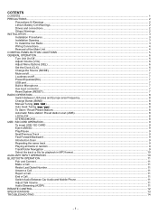
COTENTS COTENTS...1 PRECAUTIONS ...2 Precautions & Warnings ...2 Lithium Battery Cell Warnings ...2 Drives and connections ...2 Others Warnings ...2 INSTALLATION...3 Installation Procedures ...3 Installation Opening...3 To Install the Car Radio ...3 Wiring Connections ...4 Removal of the Main Unit ...4 CONTROL PANEL BUTTON LOACTIONS ...5 GENERAL OPERATION ...6 Turn Unit On/Off ...6 Adjust Volume (VOL)...6 Adjust Menu Options (SEL) ...6 Set the ...
COTENTS COTENTS...1 PRECAUTIONS ...2 Precautions & Warnings ...2 Lithium Battery Cell Warnings ...2 Drives and connections ...2 Others Warnings ...2 INSTALLATION...3 Installation Procedures ...3 Installation Opening...3 To Install the Car Radio ...3 Wiring Connections ...4 Removal of the Main Unit ...4 CONTROL PANEL BUTTON LOACTIONS ...5 GENERAL OPERATION ...6 Turn Unit On/Off ...6 Adjust Volume (VOL)...6 Adjust Menu Options (SEL) ...6 Set the ...
User Manual
Page 4
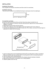
... sleeve into the mounting sleeve. 7. Installation Opening This unit can be installed in any dashboard having an opening as illustrated in the "Wiring Diagram." 9. Make sure that the lock lever is flush with a screwdriver. Install the plastic outer trim ring. - 3 - Insert...separate the chassis from the vehicle battery's negative (-) terminal. 2. Make sure the ignition is not projecting beyond. 6. Disconnect the wire harness and the antenna. 3. INSTALLATION Installation Procedures First complete the electrical connections and then check for correctness. Lift the left and...
... sleeve into the mounting sleeve. 7. Installation Opening This unit can be installed in any dashboard having an opening as illustrated in the "Wiring Diagram." 9. Make sure that the lock lever is flush with a screwdriver. Install the plastic outer trim ring. - 3 - Insert...separate the chassis from the vehicle battery's negative (-) terminal. 2. Make sure the ignition is not projecting beyond. 6. Disconnect the wire harness and the antenna. 3. INSTALLATION Installation Procedures First complete the electrical connections and then check for correctness. Lift the left and...
User Manual
Page 5
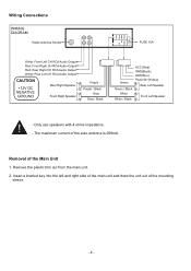
... is 200mA. Remove the plastic trim out from the main unit. 2. Only use speakers with 4 ohms impedance. - The maximum current of the Main Unit 1. Wiring Connections WIRING DIAGRAM Radio Antenna Socket 15A FUSE 15A White: Front Left CH RCA Audio Output Red: Front Right CH RCA Audio Output Red: Rear Right CH...
... is 200mA. Remove the plastic trim out from the main unit. 2. Only use speakers with 4 ohms impedance. - The maximum current of the Main Unit 1. Wiring Connections WIRING DIAGRAM Radio Antenna Socket 15A FUSE 15A White: Front Left CH RCA Audio Output Red: Front Right CH RCA Audio Output Red: Rear Right CH...


