User Manual
Page 4
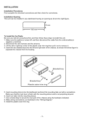
... left or right top corner of the chassis using the hardware indicated. 8. Make sure that the lock lever is flush with a screwdriver. Make wiring connections, as shown the right figure. 182 mm 53 mm To Install the Car Radio Be sure you test all connections first, and then follow...key Bracket key Plastic outer trim ring 5. Installation Opening This unit can be installed in any dashboard having an opening as illustrated in the "Wiring Diagram." 9. Disconnect the wire harness and the antenna. 3. Use a metal strap to secure the rear part of the plastic outer trim ring then pull it out to...
... left or right top corner of the chassis using the hardware indicated. 8. Make sure that the lock lever is flush with a screwdriver. Make wiring connections, as shown the right figure. 182 mm 53 mm To Install the Car Radio Be sure you test all connections first, and then follow...key Bracket key Plastic outer trim ring 5. Installation Opening This unit can be installed in any dashboard having an opening as illustrated in the "Wiring Diagram." 9. Disconnect the wire harness and the antenna. 3. Use a metal strap to secure the rear part of the plastic outer trim ring then pull it out to...
User Manual
Page 5
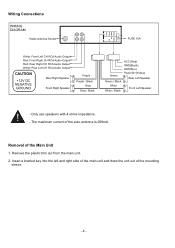
... 1. Remove the plastic trim out from the main unit. 2. Only use speakers with 4 ohms impedance. - The maximum current of the auto antenna is 200mA. Wiring Connections WIRING DIAGRAM Radio Antenna Socket 15A FUSE 15A White: Front Left CH RCA Audio Output Red: Front Right CH RCA Audio Output Red: Rear Right CH RCA...
... 1. Remove the plastic trim out from the main unit. 2. Only use speakers with 4 ohms impedance. - The maximum current of the auto antenna is 200mA. Wiring Connections WIRING DIAGRAM Radio Antenna Socket 15A FUSE 15A White: Front Left CH RCA Audio Output Red: Front Right CH RCA Audio Output Red: Rear Right CH RCA...


