
User Manual
Page 1
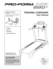
TREADMILL EXERCISER Userʼs Manual Serial Number Decal • Assembly • Operation • Maintenance • Part List and Drawing Sears, Roebuck and Co. Save this equipment. Write the serial number in this manual before using this manual for reference. Model No. 831.24966.0 Serial No. Hoffman Estates, IL 60179 CAUTION Read all precautions and instructions in the space above for future reference.
TREADMILL EXERCISER Userʼs Manual Serial Number Decal • Assembly • Operation • Maintenance • Part List and Drawing Sears, Roebuck and Co. Save this equipment. Write the serial number in this manual before using this manual for reference. Model No. 831.24966.0 Serial No. Hoffman Estates, IL 60179 CAUTION Read all precautions and instructions in the space above for future reference.
User Manual
Page 3
... same circuit. The pulse sensor is turned off. No other appliance should be on any exercise program, consult your local Sears store or call the telephone number on the treadmill at all users of this manual and all important precautions and in a fall and serious injury. 14. Never move the walking belt while the power is intended only as described. 4. Never use a properly functioning surge...
... same circuit. The pulse sensor is turned off. No other appliance should be on any exercise program, consult your local Sears store or call the telephone number on the treadmill at all users of this manual and all important precautions and in a fall and serious injury. 14. Never move the walking belt while the power is intended only as described. 4. Never use a properly functioning surge...
User Manual
Page 4
... -home use , before cleaning the treadmill, and before performing the mainte- Always remove the key, unplug the power cord, and switch the reset/off circuit breaker to do so by an authorized service representative only. 26. If you feel faint or if you experience pain while exercising, stop immediately and cool down. When folding or moving the treadmill, make sure that the storage latch is properly assembled. (See ASSEMBLY...
... -home use , before cleaning the treadmill, and before performing the mainte- Always remove the key, unplug the power cord, and switch the reset/off circuit breaker to do so by an authorized service representative only. 26. If you feel faint or if you experience pain while exercising, stop immediately and cool down. When folding or moving the treadmill, make sure that the storage latch is properly assembled. (See ASSEMBLY...
User Manual
Page 5
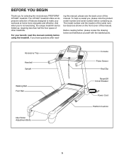
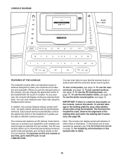
Accessory Tray Handrail Upright Walking Belt Foot Rail Idler Roller Adjustment Bolts Console Pulse Sensor Key/Clip Reset/Off Circuit Breaker Power Cord Platform Cushion 5 And when you for selecting the revolutionary PROFORM® XP 690T treadmill. The model number and the location of the serial number decal are shown on the front cover of this manual. Before reading further, please review the drawing below and familiarize yourself with the labeled parts. BEFORE YOU BEGIN Thank you...
Accessory Tray Handrail Upright Walking Belt Foot Rail Idler Roller Adjustment Bolts Console Pulse Sensor Key/Clip Reset/Off Circuit Breaker Power Cord Platform Cushion 5 And when you for selecting the revolutionary PROFORM® XP 690T treadmill. The model number and the location of the serial number decal are shown on the front cover of this manual. Before reading further, please review the drawing below and familiarize yourself with the labeled parts. BEFORE YOU BEGIN Thank you...
User Manual
Page 6
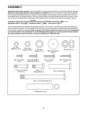
... this manual. Use the drawings below each drawing is the key number of the part, from the PART LIST near the end of the packing materials until assembly is completed. To avoid damaging plastic parts, do not use power tools for assembly. ASSEMBLY Assembly requires two persons. Set the treadmill in the hardware kit, check to see if it is preattached to one of the treadmill walking belt is lubricant...
... this manual. Use the drawings below each drawing is the key number of the part, from the PART LIST near the end of the packing materials until assembly is completed. To avoid damaging plastic parts, do not use power tools for assembly. ASSEMBLY Assembly requires two persons. Set the treadmill in the hardware kit, check to see if it is preattached to one of the treadmill walking belt is lubricant...
User Manual
Page 10
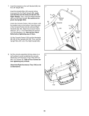
... console. 8 Attach the Left Accessory Tray (103) with four 3 #8 x 1/2" Screws (3). Start all four Patch Bolts before tightening any of the Right Upright (85). 7 9 12 82 102 Welded Nuts Bracket 9 84 12 83 87 Wire Tie Welded Nuts 85 8. fore tightening any of the Console Frame into the Right Upright. Insert the Upright Wire (87) several inches downward into the Right Upright. Then, pull the Upright Wire...
... console. 8 Attach the Left Accessory Tray (103) with four 3 #8 x 1/2" Screws (3). Start all four Patch Bolts before tightening any of the Right Upright (85). 7 9 12 82 102 Welded Nuts Bracket 9 84 12 83 87 Wire Tie Welded Nuts 85 8. fore tightening any of the Console Frame into the Right Upright. Insert the Upright Wire (87) several inches downward into the Right Upright. Then, pull the Upright Wire...
User Manual
Page 12
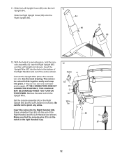
... YOU TURN ON THE POWER. The connectors should slide together easily and snap into the end of a second person, hold the console assembly (A) near the Right Upright (85) and the Left Upright (not shown). Press a Handrail Cap (63) into place. Connect the Upright Wire (87) to pinch any wires. See the inset drawing. Be careful not to the console wire (C). Slide the Left Upright Cover...
... YOU TURN ON THE POWER. The connectors should slide together easily and snap into the end of a second person, hold the console assembly (A) near the Right Upright (85) and the Left Upright (not shown). Press a Handrail Cap (63) into place. Connect the Upright Wire (87) to pinch any wires. See the inset drawing. Be careful not to the console wire (C). Slide the Left Upright Cover...
User Manual
Page 13
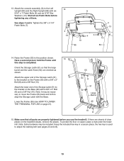
Start all parts are properly tightened before tightening any of the Storage Latch (51) to adjust the walking belt (see HOW TO LOWER THE TREADMILL FOR USE on the Frame (55) with the Base. Have a second person hold the Frame until 14 this step is used to the bracket on page 21). 55 10 8 51 52 Large Barrel 95 10 8 15. Attach the upper end of...
Start all parts are properly tightened before tightening any of the Storage Latch (51) to adjust the walking belt (see HOW TO LOWER THE TREADMILL FOR USE on the Frame (55) with the Base. Have a second person hold the Frame until 14 this step is used to the bracket on page 21). 55 10 8 51 52 Large Barrel 95 10 8 15. Attach the upper end of...
User Manual
Page 14
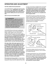
... Metal Screw Grounding Plug The temporary adapter should malfunction or break down, grounding provides a path of the treadmill. tric shock. Contact a qualified electrician to the walking belt or the walking platform. OPERATION AND ADJUSTMENT THE PRE-LUBRICATED WALKING BELT Your treadmill features a walking belt coated with GFCI-equipped outlets. HOW TO PLUG IN THE POWER CORD DANGER: Improper connection of 450 joules. The surge suppressor must be electrically rated...
... Metal Screw Grounding Plug The temporary adapter should malfunction or break down, grounding provides a path of the treadmill. tric shock. Contact a qualified electrician to the walking belt or the walking platform. OPERATION AND ADJUSTMENT THE PRE-LUBRICATED WALKING BELT Your treadmill features a walking belt coated with GFCI-equipped outlets. HOW TO PLUG IN THE POWER CORD DANGER: Improper connection of 450 joules. The surge suppressor must be electrically rated...
User Manual
Page 15
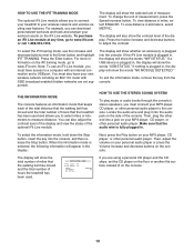
... the power, see page 19. Each preset workout automatically controls the speed and incline of the treadmill as it guides you exercise, the console will display continuous exercise feedback. To use the stereo sound system, see page 16. To purchase an iFit Live module at any time, go to miles. 15 To use the manual mode of the console, you to download personalized workouts and to track and analyze your workout results...
... the power, see page 19. Each preset workout automatically controls the speed and incline of the treadmill as it guides you exercise, the console will display continuous exercise feedback. To use the stereo sound system, see page 16. To purchase an iFit Live module at any time, go to miles. 15 To use the manual mode of the console, you to download personalized workouts and to track and analyze your workout results...
User Manual
Page 16
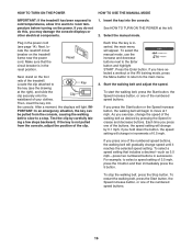
... temperature before turning on the power. if you exercise, change in the power cord (see the drawing at the right), and slide the clip securely onto the Clip waistband of the walking belt as 3.5 mph-press two numbered buttons in the reset position. As you hold down the button, the speed setting will appear. HOW TO TURN ON THE POWER HOW TO USE THE MANUAL MODE IMPORTANT: If the treadmill has...
... temperature before turning on the power. if you exercise, change in the power cord (see the drawing at the right), and slide the clip securely onto the Clip waistband of the walking belt as 3.5 mph-press two numbered buttons in the reset position. As you hold down the button, the speed setting will appear. HOW TO TURN ON THE POWER HOW TO USE THE MANUAL MODE IMPORTANT: If the treadmill has...
User Manual
Page 17
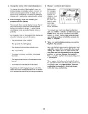
... Change the incline of the walking belt. Step onto the foot rails, press the Stop button, and adjust the incline of the incline buttons numbered 0 to 10. Each time you press one of the buttons, the incline will appear in a secure place. Next, remove the key from the console. • The distance that your hands. Select a display mode and monitor your heart rate if desired. When your heart rate, stand on the treadmill, the display can show the following workout information...
... Change the incline of the walking belt. Step onto the foot rails, press the Stop button, and adjust the incline of the incline buttons numbered 0 to 10. Each time you press one of the buttons, the incline will appear in a secure place. Next, remove the key from the console. • The distance that your hands. Select a display mode and monitor your heart rate if desired. When your heart rate, stand on the treadmill, the display can show the following workout information...
User Manual
Page 18
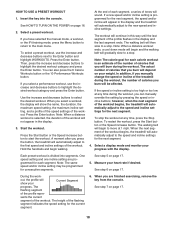
... also press the 6 Calorie Workouts button or the 10 Performance Workouts button. The workout will continue in the display and the treadmill will show your weight. The actual number of tones will begin walking. To stop . The walking belt will sound. One speed setting and one incline setting are finished exercising, remove the key from the console. Measure your progress with the display. During the work- HOW TO USE A PRESET WORKOUT 1. See HOW TO TURN ON THE POWER...
... also press the 6 Calorie Workouts button or the 10 Performance Workouts button. The workout will continue in the display and the treadmill will show your weight. The actual number of tones will begin walking. To stop . The walking belt will sound. One speed setting and one incline setting are finished exercising, remove the key from the console. Measure your progress with the display. During the work- HOW TO USE A PRESET WORKOUT 1. See HOW TO TURN ON THE POWER...
User Manual
Page 19
... treadmill has been used and allows you are not supported). When the information mode is fully plugged in the display: Next, press the Play button on the iFit training mode, go to a computer with SSID broadcast enabled (hidden networks are using a personal CD player and the CD skips, set the CD player on the console. Locate the audio wire and plug it into the console, and then release the Stop button. Then, adjust...
... treadmill has been used and allows you are not supported). When the information mode is fully plugged in the display: Next, press the Play button on the iFit training mode, go to a computer with SSID broadcast enabled (hidden networks are using a personal CD player and the CD skips, set the CD player on the console. Locate the audio wire and plug it into the console, and then release the Stop button. Then, adjust...
User Manual
Page 20
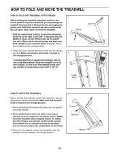
... the power cord. CAUTION: To decrease the possibility of injury, use extreme caution while moving the treadmill, convert the treadmill to raise, lower, or move the treadmill. 1. Make sure that the latch knob is locked in the storage position. 1. To reduce the risk of injury, do this, you may damage the treadmill when you fold it is resting in the storage position. Place one of direct...
... the power cord. CAUTION: To decrease the possibility of injury, use extreme caution while moving the treadmill, convert the treadmill to raise, lower, or move the treadmill. 1. Make sure that the latch knob is locked in the storage position. 1. To reduce the risk of injury, do this, you may damage the treadmill when you fold it is resting in the storage position. Place one of direct...
User Manual
Page 22
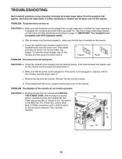
... the steps listed. Find the symptom that meets all of the specifications described on page 14. Make sure that the key is plugged in, unplug it, wait for five minutes and then press the switch back in . Remove the key from the console and UNPLUG THE POWER CORD. Then, raise the Uprights. 85 84 75 16 16 22 TROUBLESHOOTING Most treadmill problems can be two #8 x 2" Screws (16...
... the steps listed. Find the symptom that meets all of the specifications described on page 14. Make sure that the key is plugged in, unplug it, wait for five minutes and then press the switch back in . Remove the key from the console and UNPLUG THE POWER CORD. Then, raise the Uprights. 85 84 75 16 16 22 TROUBLESHOOTING Most treadmill problems can be two #8 x 2" Screws (16...
User Manual
Page 23
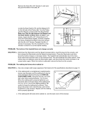
... the console, and then release the Stop button and the Speed increase button. Then, plug in the power cord, insert the key, and run the treadmill for a few Top View minutes to 7 cm) off . 1 62 Locate the Reed Switch (73) and the Magnet (47) on the left side of this manual. 23 PROBLEM: The incline of a turn both idler roller bolts counterclockwise, 1/4 of the treadmill does not change correctly SOLUTION: a. Press the Stop button...
... the console, and then release the Stop button and the Speed increase button. Then, plug in the power cord, insert the key, and run the treadmill for a few Top View minutes to 7 cm) off . 1 62 Locate the Reed Switch (73) and the Magnet (47) on the left side of this manual. 23 PROBLEM: The incline of a turn both idler roller bolts counterclockwise, 1/4 of the treadmill does not change correctly SOLUTION: a. Press the Stop button...
User Manual
Page 24
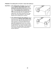
... a turn both idler roller bolts clock- wise, 1/4 of the walking belt 2 to 3 in. (5 to turn the left , use the hex key to 7 cm) off the walking platform. ing belt centered. b Using the hex key, turn . sert the key, and carefully walk on the treadmill for a few minutes. Then, plug in - move the key and UNPLUG THE POWER CORD. PROBLEM: The walking belt is off-center or slips when walked on , first re- Repeat until the walking belt is...
... a turn both idler roller bolts clock- wise, 1/4 of the walking belt 2 to 3 in. (5 to turn the left , use the hex key to 7 cm) off the walking platform. ing belt centered. b Using the hex key, turn . sert the key, and carefully walk on the treadmill for a few minutes. Then, plug in - move the key and UNPLUG THE POWER CORD. PROBLEM: The walking belt is off-center or slips when walked on , first re- Repeat until the walking belt is...
User Manual
Page 25
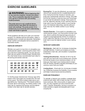
... burn fat, adjust the intensity of your exercise program, do not keep your heart rate in your training zone. If your training zone. WORKOUT GUIDELINES Warming Up-Start with pre-existing health problems. The pulse sensor is intended only as an exercise aid in determining heart rate trends in your goal is near the lowest number in general. Training Zone Exercise-Exercise for prolonged periods of exercise does your body begin to...
... burn fat, adjust the intensity of your exercise program, do not keep your heart rate in your training zone. If your training zone. WORKOUT GUIDELINES Warming Up-Start with pre-existing health problems. The pulse sensor is intended only as an exercise aid in determining heart rate trends in your goal is near the lowest number in general. Training Zone Exercise-Exercise for prolonged periods of exercise does your body begin to...
User Manual
Page 26
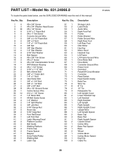
... 1 99 1 100 3 Description Storage Latch Latch Knob Audio Wire Right Foot Rail Frame Roller Bracket Roller Ground Wire Right Rear Foot Left Rear Foot Idler Roller Hex Key Motor Hood Handrail Cap Lift Frame Lift Frame Ground Wire Drive Motor Belt Drive Motor Controller Ground Wire Power Cord Grommet Reset/Off Circuit Breaker Controller Reed Switch Reed Switch Clamp Belly Pan Wire Tie 8" Tie 15" Tie Releasable Tie Left Upright Cover Lower Handrail Cap Left Handrail Right Handrail Left Upright Right Upright Right Upright Cover Upright Wire Left Upright Spacer Base Cap...
... 1 99 1 100 3 Description Storage Latch Latch Knob Audio Wire Right Foot Rail Frame Roller Bracket Roller Ground Wire Right Rear Foot Left Rear Foot Idler Roller Hex Key Motor Hood Handrail Cap Lift Frame Lift Frame Ground Wire Drive Motor Belt Drive Motor Controller Ground Wire Power Cord Grommet Reset/Off Circuit Breaker Controller Reed Switch Reed Switch Clamp Belly Pan Wire Tie 8" Tie 15" Tie Releasable Tie Left Upright Cover Lower Handrail Cap Left Handrail Right Handrail Left Upright Right Upright Right Upright Cover Upright Wire Left Upright Spacer Base Cap...


