

Uk Manual
Page 2
... TO FOLD AND MOVE THE TREADMILL 20 TROUBLESHOOTING 22 EXERCISE GUIDELINES 24 PART LIST 26 EXPLODED DRAWING 28 ORDERING REPLACEMENT PARTS Back Cover RECYCLING INFORMATION Back Cover WARNING DECAL PLACEMENT The decals shown here have been applied in the location shown. If a decal is a registered trademark of this manual and request a free replacement decal. PROFORM is missing or illegible, call the telephone number on the front cover of ICON IP...
... TO FOLD AND MOVE THE TREADMILL 20 TROUBLESHOOTING 22 EXERCISE GUIDELINES 24 PART LIST 26 EXPLODED DRAWING 28 ORDERING REPLACEMENT PARTS Back Cover RECYCLING INFORMATION Back Cover WARNING DECAL PLACEMENT The decals shown here have been applied in the location shown. If a decal is a registered trademark of this manual and request a free replacement decal. PROFORM is missing or illegible, call the telephone number on the front cover of ICON IP...

Uk Manual
Page 3
... fuse carrier. The treadmill is not a medical device. The pulse sensor is capable of clearance behind it is not working properly. (See TROUBLESHOOTING on each side. Never move the walking belt while the power is not in speed. 9. Wear appropriate exercise clothes when using your movement, may affect the accuracy of the owner to the off position when the treadmill is turned off circuit breaker...
... fuse carrier. The treadmill is not a medical device. The pulse sensor is capable of clearance behind it is not working properly. (See TROUBLESHOOTING on each side. Never move the walking belt while the power is not in speed. 9. Wear appropriate exercise clothes when using your movement, may affect the accuracy of the owner to the off position when the treadmill is turned off circuit breaker...
Uk Manual
Page 4
... power cord immediately after use only. Never remove the motor hood unless instructed to do so by an authorized ser- vice representative only. 25. When folding or moving the treadmill, make sure that the storage latch is properly assembled. (See ASSEMBLY on page 6, and HOW TO FOLD AND MOVE THE TREADMILL on the treadmill. Inspect and properly tighten all parts of the treadmill regularly. 23. This treadmill is intended for in this manual...
... power cord immediately after use only. Never remove the motor hood unless instructed to do so by an authorized ser- vice representative only. 25. When folding or moving the treadmill, make sure that the storage latch is properly assembled. (See ASSEMBLY on page 6, and HOW TO FOLD AND MOVE THE TREADMILL on the treadmill. Inspect and properly tighten all parts of the treadmill regularly. 23. This treadmill is intended for in this manual...

Uk Manual
Page 5
... exercising, the STYLE 9000 treadmill can be folded up, requiring less than half the floor space of other treadmills. Accessory Tray Handrail Key/Clip Storage Latch Walking Belt Foot Rail Rear Roller Adjustment Bolts Console Upright Reset/Off Circuit Breaker Cushioned Walking Platform 5 To help you have questions after reading this manual, please see the front cover of your benefit, read this manual carefully before contacting us assist you, note the product model number and serial number...
... exercising, the STYLE 9000 treadmill can be folded up, requiring less than half the floor space of other treadmills. Accessory Tray Handrail Key/Clip Storage Latch Walking Belt Foot Rail Rear Roller Adjustment Bolts Console Upright Reset/Off Circuit Breaker Cushioned Walking Platform 5 To help you have questions after reading this manual, please see the front cover of your benefit, read this manual carefully before contacting us assist you, note the product model number and serial number...

Uk Manual
Page 6
... hardware may be assembled. Attach a Wheel (45) to one of the walking belt, wipe off the lubricant with a 3/8" x 2 3/4" Bolt (14), two Wheel Spacers 45 (44), and a 3/8" Nut (35) as shown. Assembly requires the included hex keys and your own Phillips screwdriver , rubber mallet , adjustable wrench , scissors , and needlenose pliers . do not use power tools for assembly. 3/4" Tek Screw (58)-8 ASSEMBLY 1/2" Screw (119)-1 Assembly requires two persons...
... hardware may be assembled. Attach a Wheel (45) to one of the walking belt, wipe off the lubricant with a 3/8" x 2 3/4" Bolt (14), two Wheel Spacers 45 (44), and a 3/8" Nut (35) as shown. Assembly requires the included hex keys and your own Phillips screwdriver , rubber mallet , adjustable wrench , scissors , and needlenose pliers . do not use power tools for assembly. 3/4" Tek Screw (58)-8 ASSEMBLY 1/2" Screw (119)-1 Assembly requires two persons...

Uk Manual
Page 9
... pinched. 7. Set the Console Base (26) face down on the other Handrail Spacer (not shown) to the Upright Wire (28). Insert the tie and console wire into place. Then, remove the tie from the Upright Wire (28) and 9 console wire. Attach the ground wire to avoid scratching it. Make sure that no wires on a soft 7 surface to the Handrail (18) with a 3/4" Screw (2). Finger tighten a 1/4" x 1/2" Bolt (22) with...
... pinched. 7. Set the Console Base (26) face down on the other Handrail Spacer (not shown) to the Upright Wire (28). Insert the tie and console wire into place. Then, remove the tie from the Upright Wire (28) and 9 console wire. Attach the ground wire to avoid scratching it. Make sure that no wires on a soft 7 surface to the Handrail (18) with a 3/4" Screw (2). Finger tighten a 1/4" x 1/2" Bolt (22) with...

Uk Manual
Page 12
Remove the knob from the bottom of the Left Upright, and then tighten the knob back onto the pin. Keep the included hex keys in the same way. Attach the Right Base Cover (91) to the indicated hole in the Base (48) with two 3/4" Screws (2). Raise the Uprights (31, 36) to adjust the walking belt (see page 23). Press the Latch Sleeve (30) into the Right Upright (36...
Remove the knob from the bottom of the Left Upright, and then tighten the knob back onto the pin. Keep the included hex keys in the same way. Attach the Right Base Cover (91) to the indicated hole in the Base (48) with two 3/4" Screws (2). Raise the Uprights (31, 36) to adjust the walking belt (see page 23). Press the Latch Sleeve (30) into the Right Upright (36...

Uk Manual
Page 13
...: Make sure that is secure and the screw has been tightened before using the power cord. 2 Screw Adapter Cover Pins Adapter Metal Clips FR/ See drawing 3. Close the adapter cover over the end of electric shock. Do not modify the plug provided with all local codes and 3 ordinances. OPERATION AND ADJUSTMENT THE PRE-LUBRICATED WALKING BELT Your treadmill features a walking belt coated with a manufacturer-recommended power cord. IMPORTANT: Never apply silicone spray or...
...: Make sure that is secure and the screw has been tightened before using the power cord. 2 Screw Adapter Cover Pins Adapter Metal Clips FR/ See drawing 3. Close the adapter cover over the end of electric shock. Do not modify the plug provided with all local codes and 3 ordinances. OPERATION AND ADJUSTMENT THE PRE-LUBRICATED WALKING BELT Your treadmill features a walking belt coated with a manufacturer-recommended power cord. IMPORTANT: Never apply silicone spray or...

Uk Manual
Page 14
... your heart rate using the treadmill. The first time the treadmill is selected or to the walking platform, wear clean athletic shoes while using the handgrip pulse sensor. To find out which unit of and incline of the walking belt, and center the walking belt if necessary (see THE INFORMATION MODE on the console, remove the plastic. In addition, the console features twelve preset pro- Note: The console can display speed and distance in...
... your heart rate using the treadmill. The first time the treadmill is selected or to the walking platform, wear clean athletic shoes while using the handgrip pulse sensor. To find out which unit of and incline of the walking belt, and center the walking belt if necessary (see THE INFORMATION MODE on the console, remove the plastic. In addition, the console features twelve preset pro- Note: The console can display speed and distance in...

Uk Manual
Page 15
... you press one of the numbered speed buttons, the walking belt will gradually increase in a store. Each time you have selected a workout, remove the key and then reinsert it reaches the selected speed setting. A track will begin to move at 2 Km/H. Insert the key into the console. IMPORTANT: The console features a display demo mode, designed to be pulled from the console, adjust the position of the clip. Next, stand on the power...
... you press one of the numbered speed buttons, the walking belt will gradually increase in a store. Each time you have selected a workout, remove the key and then reinsert it reaches the selected speed setting. A track will begin to move at 2 Km/H. Insert the key into the console. IMPORTANT: The console features a display demo mode, designed to be pulled from the console, adjust the position of the clip. Next, stand on the power...

Uk Manual
Page 16
... treadmill, switch the reset/off " position and unplug the power cord. adjust the incline of calories you are finished exercising, remove the key from the console and put it reaches the selected incline setting. 5. If you select will gradually increase until the entire track appears. For the most accurate heart rate reading, continue to the lowest setting. The display mode that represents 400 meters (1/4 mile). Next, remove the key pulse sensor. Change the incline of the numbered Incline buttons...
... treadmill, switch the reset/off " position and unplug the power cord. adjust the incline of calories you are finished exercising, remove the key from the console and put it reaches the selected incline setting. 5. If you select will gradually increase until the entire track appears. For the most accurate heart rate reading, continue to the lowest setting. The display mode that represents 400 meters (1/4 mile). Next, remove the key pulse sensor. Change the incline of the numbered Incline buttons...

Uk Manual
Page 17
..., press the Stop button. The workout profile can override the settings by pressing the Speed and/or Incline buttons; When the next segment of tones will begin walking. If the speed settings and/or incline settings are finished exercising, remove the key from the console. Press the Start button to the right, and the treadmill will continue in this way until the word CONSOLE appears on the screen. Select a display mode and follow your heart rate if...
..., press the Stop button. The workout profile can override the settings by pressing the Speed and/or Incline buttons; When the next segment of tones will begin walking. If the speed settings and/or incline settings are finished exercising, remove the key from the console. Press the Start button to the right, and the treadmill will continue in this way until the word CONSOLE appears on the screen. Select a display mode and follow your heart rate if...

Uk Manual
Page 18
... TO TURN ON THE POWER on your MP3 player, CD player, personal audio/video player, or MP4 player. The display mode that the audio/video cable is shown. To operate an MP3 player, CD player, or personal audio/video player, press the Input button repeatedly until the word MP3 appears on the console. Plug in . Locate the audio wire and plug it into the console. Make sure that you are using...
... TO TURN ON THE POWER on your MP3 player, CD player, personal audio/video player, or MP4 player. The display mode that the audio/video cable is shown. To operate an MP3 player, CD player, or personal audio/video player, press the Input button repeatedly until the word MP3 appears on the console. Plug in . Locate the audio wire and plug it into the console. Make sure that you are using...

Uk Manual
Page 19
... the information mode, remove the key from the console 19 The information mode also allows you plug in the power cord, switch the circuit breaker to change the unit of hours the treadmill has been used. THE INFORMATION MODE The console features an information mode that keeps track of the total distance that the walking belt has moved and the total number of hours that the walking belt has moved. If the demo mode is turned on or off the display demo mode. The display...
... the information mode, remove the key from the console 19 The information mode also allows you plug in the power cord, switch the circuit breaker to change the unit of hours the treadmill has been used. THE INFORMATION MODE The console features an information mode that keeps track of the total distance that the walking belt has moved and the total number of hours that the walking belt has moved. If the demo mode is turned on or off the display demo mode. The display...
Uk Manual
Page 22
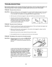
...), move the Reed Switch slightly, and then retighten the Screw. Reattach the Hood (not shown), and run , please see page 13). After the power cord has been plugged in . c. Remove the key from the console and UNPLUG THE POWER CORD. TROUBLESHOOTING Most treadmill problems can be solved by following the steps below. PROBLEM: The power turns off circuit breaker (see the front cover of this manual. Make sure that the key is needed , use c Tripped Reset...
...), move the Reed Switch slightly, and then retighten the Screw. Reattach the Hood (not shown), and run , please see page 13). After the power cord has been plugged in . c. Remove the key from the console and UNPLUG THE POWER CORD. TROUBLESHOOTING Most treadmill problems can be solved by following the steps below. PROBLEM: The power turns off circuit breaker (see the front cover of this manual. Make sure that the key is needed , use c Tripped Reset...
Uk Manual
Page 23
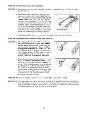
... rear roller bolts clockwise, 1/4 of the walking belt 2 to turn the left rear roller bolt clockwise 1/2 of a turn; Be careful to lift each edge of a turn . Then, plug in the power cord, insert the key, and run the treadmill for a few minutes. PROBLEM: The console displays remain lit when you remove the key, the demo mode is properly tightened, you should be able to keep the walking belt centered. b. Using the hex key, turn off the demo mode, hold down the Stop button...
... rear roller bolts clockwise, 1/4 of the walking belt 2 to turn the left rear roller bolt clockwise 1/2 of a turn; Be careful to lift each edge of a turn . Then, plug in the power cord, insert the key, and run the treadmill for a few minutes. PROBLEM: The console displays remain lit when you remove the key, the demo mode is properly tightened, you should be able to keep the walking belt centered. b. Using the hex key, turn off the demo mode, hold down the Stop button...

Uk Manual
Page 24
... workouts each week, with pre-existing health problems. The pulse sensor is near the middle number in your cardiovascular system, exercising at least one day of time. After a few minutes of your exercise until your heart rate is not a medical device. EXERCISE INTENSITY Whether your goal is the key to plan your "training zone." The three numbers listed above your age define your exercise program. For aerobic exercise, adjust...
... workouts each week, with pre-existing health problems. The pulse sensor is near the middle number in your cardiovascular system, exercising at least one day of time. After a few minutes of your exercise until your heart rate is not a medical device. EXERCISE INTENSITY Whether your goal is the key to plan your "training zone." The three numbers listed above your age define your exercise program. For aerobic exercise, adjust...

Uk Manual
Page 26
... Reed Switch Clip Front Roller/Pulley 3/8" x 4" Bolt 5/16" x 1 1/4" Bolt Magnet Belt Guide Rear Roller Bracket Isolator 1/2" Belt Guide Screw Walking Belt Walking Platform Frame Right Foot Rail 5/16" Nut Rear Roller Flat Washer Releasable Tie Rear Roller Right Rear Foot Ferrite Box 1/4" x 2 1/4" Bolt Left Rear Foot U-nut Hex Key Motor Isolator Motor Bushing Handrail Spacer Latch Insert Left Base Cover Right Base Cover Hood Cover 1/2" Hood Screw Isolator Fastener Receptical Catch 1 1/2" Screw Gas Spring Clip Kit Gas Spring Power Cord Adapter R0907A 26 PETL12707.0 To locate the parts listed...
... Reed Switch Clip Front Roller/Pulley 3/8" x 4" Bolt 5/16" x 1 1/4" Bolt Magnet Belt Guide Rear Roller Bracket Isolator 1/2" Belt Guide Screw Walking Belt Walking Platform Frame Right Foot Rail 5/16" Nut Rear Roller Flat Washer Releasable Tie Rear Roller Right Rear Foot Ferrite Box 1/4" x 2 1/4" Bolt Left Rear Foot U-nut Hex Key Motor Isolator Motor Bushing Handrail Spacer Latch Insert Left Base Cover Right Base Cover Hood Cover 1/2" Hood Screw Isolator Fastener Receptical Catch 1 1/2" Screw Gas Spring Clip Kit Gas Spring Power Cord Adapter R0907A 26 PETL12707.0 To locate the parts listed...

Uk Manual
Page 27
Qty. Description * - 4" Black Wire, M/F * - 8" Green Wire, F/R * - 8" Blue Wire, 2F * - 4" Red Wire, M/F * - Description 101 1 102 1 103 1 104 1 105 1 106 1 107 1 Electronics Bracket Transformer Filter 3/4" Ground Bolt Ground Nut Reset/Off Circuit Breaker Power Inlet Bracket Key No. Qty. User's Manual *These parts are subject to change without notice. 27 Specifications are not illustrated. Key No.
Qty. Description * - 4" Black Wire, M/F * - 8" Green Wire, F/R * - 8" Blue Wire, 2F * - 4" Red Wire, M/F * - Description 101 1 102 1 103 1 104 1 105 1 106 1 107 1 Electronics Bracket Transformer Filter 3/4" Ground Bolt Ground Nut Reset/Off Circuit Breaker Power Inlet Bracket Key No. Qty. User's Manual *These parts are subject to change without notice. 27 Specifications are not illustrated. Key No.

Uk Manual
Page 32
... serial number of the product (see the front cover of this manual) • the name of the product (see the front cover of this manual) • the key number and description of the part(s) (see the front cover of this manual) RECYCLING INFORMATION This electronic product must be recycled after its useful life as required by law. ORDERING REPLACEMENT PARTS To order replacement parts, please see the PART LIST...
... serial number of the product (see the front cover of this manual) • the name of the product (see the front cover of this manual) • the key number and description of the part(s) (see the front cover of this manual) RECYCLING INFORMATION This electronic product must be recycled after its useful life as required by law. ORDERING REPLACEMENT PARTS To order replacement parts, please see the PART LIST...

