

English Manual
Page 2
...actual size. Note: The decal is missing or illegible, see the front cover of this manual and request a free replacement decal. PROFORM is a registered trademark of the warning decal. Apply the decal in the location shown. TABLE OF CONTENTS WARNING DECAL PLACEMENT 2 ...IMPORTANT PRECAUTIONS 3 BEFORE YOU BEGIN 7 PART IDENTIFICATION CHART 8 ASSEMBLY 9 THE CHEST HEART RATE MONITOR 18 OPERATION AND ADJUSTMENT 19 HOW TO MOVE THE TREADMILL 33 TROUBLESHOOTING 34 EXERCISE GUIDELINES 36 PART LIST 38 EXPLODED DRAWING 40 ORDERING REPLACEMENT PARTS Back...
...actual size. Note: The decal is missing or illegible, see the front cover of this manual and request a free replacement decal. PROFORM is a registered trademark of the warning decal. Apply the decal in the location shown. TABLE OF CONTENTS WARNING DECAL PLACEMENT 2 ...IMPORTANT PRECAUTIONS 3 BEFORE YOU BEGIN 7 PART IDENTIFICATION CHART 8 ASSEMBLY 9 THE CHEST HEART RATE MONITOR 18 OPERATION AND ADJUSTMENT 19 HOW TO MOVE THE TREADMILL 33 TROUBLESHOOTING 34 EXERCISE GUIDELINES 36 PART LIST 38 EXPLODED DRAWING 40 ORDERING REPLACEMENT PARTS Back...

English Manual
Page 4
Never leave the treadmill unattended while it is properly assembled. (See ASSEMBLY on page 9, and HOW TO MOVE THE TREADMILL on page 33.) You must be performed by an authorized service representative. Always unplug the power cord immediately after use . 24. Do not attempt to move the treadmill. 26. vice representative only. 22. Over exercising may...
Never leave the treadmill unattended while it is properly assembled. (See ASSEMBLY on page 9, and HOW TO MOVE THE TREADMILL on page 33.) You must be performed by an authorized service representative. Always unplug the power cord immediately after use . 24. Do not attempt to move the treadmill. 26. vice representative only. 22. Over exercising may...

English Manual
Page 8
Note: If a part is not in parentheses below to see if it is the quantity used for assembly. PART IDENTIFICATION CHART Use the drawings below each drawing is the key number of the part, from the PART LIST near the end of this ..." x 5/8" Screw (6)–-2 Screw (3)–-4 5/16" x 3/4" Screw (105)–-4 3/8" x 2 3/4" Bolt (1)–-2 3/8" x 4 1/4" Screw (2)–-2 8 The number in the hardware kit, check to identify small parts used for assembly.
Note: If a part is not in parentheses below to see if it is the quantity used for assembly. PART IDENTIFICATION CHART Use the drawings below each drawing is the key number of the part, from the PART LIST near the end of this ..." x 5/8" Screw (6)–-2 Screw (3)–-4 5/16" x 3/4" Screw (105)–-4 3/8" x 2 3/4" Bolt (1)–-2 3/8" x 4 1/4" Screw (2)–-2 8 The number in the hardware kit, check to identify small parts used for assembly.
English Manual
Page 9
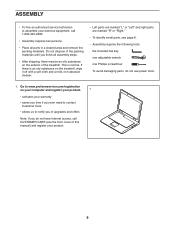
...normal. Go to www.proformservice.com/registration on the exterior of the treadmill. ASSEMBLY •• To hire an authorized service technician to notify you ...of the packing materials until you do not use power tools. 1. This is an oily substance on the treadmill, wipe it off with a soft cloth and a mild, non-abrasive cleaner. •• Left parts ...148;" or “"Right.”" •• To identify small parts, see page 8. •• Assembly requires the following tools: the included hex key one adjustable wrench one Phillips screwdriver To avoid damaging parts, do...
...normal. Go to www.proformservice.com/registration on the exterior of the treadmill. ASSEMBLY •• To hire an authorized service technician to notify you ...of the packing materials until you do not use power tools. 1. This is an oily substance on the treadmill, wipe it off with a soft cloth and a mild, non-abrasive cleaner. •• Left parts ...148;" or “"Right.”" •• To identify small parts, see page 8. •• Assembly requires the following tools: the included hex key one adjustable wrench one Phillips screwdriver To avoid damaging parts, do...

English Manual
Page 11
...is not a wire in the bottom of the right handrail, and pull it out of the front of the right handrail. Set the console assembly face-down on a soft surface to avoid scratching the console. 5 Attach the Left and Right Trays (97, 98) to the console... Washers (10). Insert the Upright Wire (78) into the large hole in the Left Upright (80). Attach the left handrail assemblies (A, B). 4 C 10 3 B 10 3 80 78 A C 10 3 10 3 81 5. Set the right handrail assembly (A) onto the Right Upright (81), and attach the right handrail with six #8 x 1/2" Screws (4). 4 Do not overtighten the Screws...
...is not a wire in the bottom of the right handrail, and pull it out of the front of the right handrail. Set the console assembly face-down on a soft surface to avoid scratching the console. 5 Attach the Left and Right Trays (97, 98) to the console... Washers (10). Insert the Upright Wire (78) into the large hole in the Left Upright (80). Attach the left handrail assemblies (A, B). 4 C 10 3 B 10 3 80 78 A C 10 3 10 3 81 5. Set the right handrail assembly (A) onto the Right Upright (81), and attach the right handrail with six #8 x 1/2" Screws (4). 4 Do not overtighten the Screws...

English Manual
Page 12
Remove and discard the four 5/16" x 5/8" Screws (3). 6 Console Assembly D D 3 3 D 77 7. Remove and discard the four screws (D). B Remove the wire tie from the Upright Wire (78). 77 7 A 78 Wire Tie 1 2 12 Next, lift off the ... (2) (only one side is shown). Start all four Screws, and then tighten them. Slide the Pulse Bar Bottom (77) onto the right and left handrail assemblies (A, B) as far as pos- 7 sible in the direction shown. 6. Attach the Pulse Bar Bottom (77) with four #10 x 3/4" Screws (7).
Remove and discard the four 5/16" x 5/8" Screws (3). 6 Console Assembly D D 3 3 D 77 7. Remove and discard the four screws (D). B Remove the wire tie from the Upright Wire (78). 77 7 A 78 Wire Tie 1 2 12 Next, lift off the ... (2) (only one side is shown). Start all four Screws, and then tighten them. Slide the Pulse Bar Bottom (77) onto the right and left handrail assemblies (A, B) as far as pos- 7 sible in the direction shown. 6. Attach the Pulse Bar Bottom (77) with four #10 x 3/4" Screws (7).

English Manual
Page 13
8. Route the Upright Wire (78) as shown so that it does not get pinched as you set the console 9 assembly onto the right handrail assembly (B) and the left handrail assembly (not shown). The connectors should slide together easily and snap into place. If they do not, turn one connector and try ...again. Connect the Upright Wire (78) to the console wire. See the inset drawing. Console Assembly Console 78 Wire Plastic Ties 81 Console 78 Wire 78 B Console Assembly 13 IF YOU DO NOT CONNECT THE CONNECTORS PROPERLY, THE CONSOLE MAY BECOME DAMAGED WHEN YOU TURN ON THE...
8. Route the Upright Wire (78) as shown so that it does not get pinched as you set the console 9 assembly onto the right handrail assembly (B) and the left handrail assembly (not shown). The connectors should slide together easily and snap into place. If they do not, turn one connector and try ...again. Connect the Upright Wire (78) to the console wire. See the inset drawing. Console Assembly Console 78 Wire Plastic Ties 81 Console 78 Wire 78 B Console Assembly 13 IF YOU DO NOT CONNECT THE CONNECTORS PROPERLY, THE CONSOLE MAY BECOME DAMAGED WHEN YOU TURN ON THE...

English Manual
Page 14
Then, tighten the four 5/16" x 5/8" Screws (3). 104 103 3 105 Console Assembly 104 103 105 3 14 Tighten four #8 x 3/4" Screws (5) into the bottom of the Pulse Bar Bottom (77). 10 Console Assembly 5 5 77 5 11. Attach the console assembly with four 5/16" x 3/4" Screws (105), four 5/16" Flat Washers 11 (103), and four 3/8" External Star Washers (104) as shown. Start all four Screws, and then tighten them. 10.
Then, tighten the four 5/16" x 5/8" Screws (3). 104 103 3 105 Console Assembly 104 103 105 3 14 Tighten four #8 x 3/4" Screws (5) into the bottom of the Pulse Bar Bottom (77). 10 Console Assembly 5 5 77 5 11. Attach the console assembly with four 5/16" x 3/4" Screws (105), four 5/16" Flat Washers 11 (103), and four 3/8" External Star Washers (104) as shown. Start all four Screws, and then tighten them. 10.

English Manual
Page 15
Attach the Left Handrail Bottom (73) to the bottom of the left handrail assembly (B) with four #8 x 3/4" Screws (5). A 73 5 13. Start all four Screws, and then tighten them. 79 74 5 81 5 80 5 15 12. Attach the Center Tray (79) to the tray brackets on the Right Upright (81) and the Left Upright 13 (80) with two #8 x 3/4" Screws (5). B tom of the right handrail assembly (A) with two 12 #8 x 3/4" Screws (5). Attach the Right Handrail Bottom (74) to the bot-
Attach the Left Handrail Bottom (73) to the bottom of the left handrail assembly (B) with four #8 x 3/4" Screws (5). A 73 5 13. Start all four Screws, and then tighten them. 79 74 5 81 5 80 5 15 12. Attach the Center Tray (79) to the tray brackets on the Right Upright (81) and the Left Upright 13 (80) with two #8 x 3/4" Screws (5). B tom of the right handrail assembly (A) with two 12 #8 x 3/4" Screws (5). Attach the Right Handrail Bottom (74) to the bot-

English Manual
Page 17
...) down against the console assembly. 6 92 Console 91 Assembly 17. See HOW TO MOVE THE TREADMILL on the iPad Holder (92). To protect the floor or carpet, place a mat under the treadmill. Nuts Leveling Feet 18. If there are properly tightened before you use the treadmill. Slide the iPad Holder...foot clockwise or counterclockwise until the rocking motion is used to the 16 console assembly with two 1/4" x 1/2" Screws (6). Attach the iPad Holder to adjust the walking belt (see page 35). 17 If the treadmill rocks even slightly, loosen one of plastic on the floor. Make sure ...
...) down against the console assembly. 6 92 Console 91 Assembly 17. See HOW TO MOVE THE TREADMILL on the iPad Holder (92). To protect the floor or carpet, place a mat under the treadmill. Nuts Leveling Feet 18. If there are properly tightened before you use the treadmill. Slide the iPad Holder...foot clockwise or counterclockwise until the rocking motion is used to the 16 console assembly with two 1/4" x 1/2" Screws (6). Attach the iPad Holder to adjust the walking belt (see page 35). 17 If the treadmill rocks even slightly, loosen one of plastic on the floor. Make sure ...


