

User Manual
Page 1
Write the serial number in this manual before using this manual for reference. Keep this equipment. Serial Number Decal (on underside of frame) QUESTIONS? www.proform.com If you have questions, or if parts are damaged or missing, PLEASE CONTACT OUR CUSTOMER SERVICE DEPARTMENT DIRECTLY. Model No. PFCCEL57909.0 Serial No. CALL TOLL-FREE: 1-888-936-4266 Mon.-Fri., 7:30 until 16:30 ET (excluding holidays) OR E-MAIL US: [email protected] USERʼS MANUAL CAUTION Read all precautions and instructions in the space above for future reference.
Write the serial number in this manual before using this manual for reference. Keep this equipment. Serial Number Decal (on underside of frame) QUESTIONS? www.proform.com If you have questions, or if parts are damaged or missing, PLEASE CONTACT OUR CUSTOMER SERVICE DEPARTMENT DIRECTLY. Model No. PFCCEL57909.0 Serial No. CALL TOLL-FREE: 1-888-936-4266 Mon.-Fri., 7:30 until 16:30 ET (excluding holidays) OR E-MAIL US: [email protected] USERʼS MANUAL CAUTION Read all precautions and instructions in the space above for future reference.

User Manual
Page 2
...3 BEFORE YOU BEGIN 4 ASSEMBLY 5 HOW TO USE THE ELLIPTICAL EXERCISER 12 MAINTENANCE AND TROUBLESHOOTING 20 EXERCISE GUIDELINES 21 PART LIST 23 EXPLODED DRAWING 25 ORDERING REPLACEMENT PARTS Back Cover LIMITED WARRANTY Back Cover WARNING DECAL PLACEMENT This drawing shows the location(s) of this manual and request a free replacement decal. Keep hands and ... Apply the decal in the location shown. Note: The decal(s) may not be shown at actual size. If a decal is a registered trademark of this area. PROFORM is missing or illegible, see the front cover of ICON IP, Inc. 2
...3 BEFORE YOU BEGIN 4 ASSEMBLY 5 HOW TO USE THE ELLIPTICAL EXERCISER 12 MAINTENANCE AND TROUBLESHOOTING 20 EXERCISE GUIDELINES 21 PART LIST 23 EXPLODED DRAWING 25 ORDERING REPLACEMENT PARTS Back Cover LIMITED WARRANTY Back Cover WARNING DECAL PLACEMENT This drawing shows the location(s) of this manual and request a free replacement decal. Keep hands and ... Apply the decal in the location shown. Note: The decal(s) may not be shown at actual size. If a decal is a registered trademark of this area. PROFORM is missing or illegible, see the front cover of ICON IP, Inc. 2

User Manual
Page 3
... all users of the elliptical exerciser are adequately informed of all precautions. 3. If you feel faint or if you stop immediately and cool down. 14. It is intended only as described in this manual. 3 Do not use of this product. 1. Hold the upper body arms or the handlebars when mounting, dismounting, or using your elliptical exerciser only as an exercise aid in determining heart rate...
... all users of the elliptical exerciser are adequately informed of all precautions. 3. If you feel faint or if you stop immediately and cool down. 14. It is intended only as described in this manual. 3 Do not use of this product. 1. Hold the upper body arms or the handlebars when mounting, dismounting, or using your elliptical exerciser only as an exercise aid in determining heart rate...

User Manual
Page 4
... Pulse Sensor Upper Body Arm Ramp Handle Pedal Ramp Handle Wheel Roller *Water bottle is not included 4 BEFORE YOU BEGIN Thank you , note the product model number and serial number before you have questions after reading this manual, please see the front cover of this manual. If you use the elliptical exerciser. To help us assist you for selecting the new PROFORM® 785 F elliptical exerciser. For your workouts at home more...
... Pulse Sensor Upper Body Arm Ramp Handle Pedal Ramp Handle Wheel Roller *Water bottle is not included 4 BEFORE YOU BEGIN Thank you , note the product model number and serial number before you have questions after reading this manual, please see the front cover of this manual. If you use the elliptical exerciser. To help us assist you for selecting the new PROFORM® 785 F elliptical exerciser. For your workouts at home more...

User Manual
Page 5
... assembly is the quantity needed for assembly. Place all parts of this manual. The number following the parentheses is completed. In addition to the included tool(s), assembly requires a Phillips screwdriver wrench , and a rubber mallet . , an adjustable As you assemble the elliptical exerciser, use the drawings below each drawing is not in the hardware kit, check to identify small parts. Note: If a part is the key number...
... assembly is the quantity needed for assembly. Place all parts of this manual. The number following the parentheses is completed. In addition to the included tool(s), assembly requires a Phillips screwdriver wrench , and a rubber mallet . , an adjustable As you assemble the elliptical exerciser, use the drawings below each drawing is not in the hardware kit, check to identify small parts. Note: If a part is the key number...
User Manual
Page 6
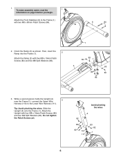
... 3. Tip: Avoid pinching the wires. Slide the Upright (4) onto the Frame (1). Avoid pinching the wires 4 82 83 82 110 111 83 82 1 6 Then, insert the 2 Ramp into the Frame (1). To make assembly easier, read the 1 information on page 5 before you begin. Do not tighten the Patch Screws yet. 1. Attach the Upright with four M8 x 19mm Patch Screws (82) and four...
... 3. Tip: Avoid pinching the wires. Slide the Upright (4) onto the Frame (1). Avoid pinching the wires 4 82 83 82 110 111 83 82 1 6 Then, insert the 2 Ramp into the Frame (1). To make assembly easier, read the 1 information on page 5 before you begin. Do not tighten the Patch Screws yet. 1. Attach the Upright with four M8 x 19mm Patch Screws (82) and four...
User Manual
Page 11
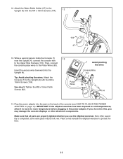
... parts may damage the console displays or other electronic components. Then, connect the console pulse wires to the Upright (4) with four M4 x 16mm Screws (104). See step 3. Plug the power adapter into the Upright (4). Place a mat beneath the elliptical exerciser to the Upper Wire Harness (110). While a second person holds the Console (7) 13 near the Upright (4), connect the console wire to protect the floor. 11 If you do not do this, you use...
... parts may damage the console displays or other electronic components. Then, connect the console pulse wires to the Upright (4) with four M4 x 16mm Screws (104). See step 3. Plug the power adapter into the Upright (4). Place a mat beneath the elliptical exerciser to the Upper Wire Harness (110). While a second person holds the Console (7) 13 near the Upright (4), connect the console wire to protect the floor. 11 If you do not do this, you use...
User Manual
Page 12
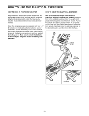
... of the console. HOW TO USE THE ELLIPTICAL EXERCISER HOW TO PLUG IN THE POWER ADAPTER HOW TO MOVE THE ELLIPTICAL EXERCISER Plug one of the front wheels. Remove the battery cover, insert the batteries into the jack on upright Place your foot here Lift here 12 Due to orient the batteries as shown by the diagrams inside the battery compartment. Carefully move the elliptical exerciser to the desired location, and then lower it...
... of the console. HOW TO USE THE ELLIPTICAL EXERCISER HOW TO PLUG IN THE POWER ADAPTER HOW TO MOVE THE ELLIPTICAL EXERCISER Plug one of the front wheels. Remove the battery cover, insert the batteries into the jack on upright Place your foot here Lift here 12 Due to orient the batteries as shown by the diagrams inside the battery compartment. Carefully move the elliptical exerciser to the desired location, and then lower it...
User Manual
Page 13
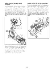
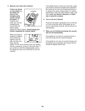
... elliptical exerciser, wait until the pedals come to move with a continuous motion. Note: The crank arms can turn the crank arms in either direction. Push the pedals until the flywheel stops. To change the incline of the pedals, you can change the incline, press the latch button, pull the ramp handle, and raise or lower the ramp to move until they begin to the desired incline level. When the pedals are stationary, step off the lower pedal...
... elliptical exerciser, wait until the pedals come to move with a continuous motion. Note: The crank arms can turn the crank arms in either direction. Push the pedals until the flywheel stops. To change the incline of the pedals, you can change the incline, press the latch button, pull the ramp handle, and raise or lower the ramp to move until they begin to the desired incline level. When the pedals are stationary, step off the lower pedal...

User Manual
Page 14
... you exercise, the console will display continuous exercise feedback. CONSOLE DIAGRAM FEATURES OF THE CONSOLE The revolutionary console offers an array of a button. While you exercise. You can change console settings, see page 18. You can even connect your MP3 player or CD player to the consoleʼs sound system and listen to make your heart rate using the handgrip pulse sensor. To randomly select a workout, see page 19. To use a trainer workout, see...
... you exercise, the console will display continuous exercise feedback. CONSOLE DIAGRAM FEATURES OF THE CONSOLE The revolutionary console offers an array of a button. While you exercise. You can change console settings, see page 18. You can even connect your MP3 player or CD player to the consoleʼs sound system and listen to make your heart rate using the handgrip pulse sensor. To randomly select a workout, see page 19. To use a trainer workout, see...

User Manual
Page 15
... display can show a track representing 1/4 mile (402 meters). Select the manual mode. The lower left display-As you exercise, the lower left or lower right display. As you have selected a workout, reselect the manual mode by pressing the Resistance increase and decrease buttons. The display also shows your progress with the display. A moment after you use the handgrip pulse sensor (see HOW TO CHANGE CONSOLE SETTINGS on page 16). Note: The console can show the your pedaling speed...
... display can show a track representing 1/4 mile (402 meters). Select the manual mode. The lower left display-As you exercise, the lower left or lower right display. As you have selected a workout, reselect the manual mode by pressing the Resistance increase and decrease buttons. The display also shows your progress with the display. A moment after you use the handgrip pulse sensor (see HOW TO CHANGE CONSOLE SETTINGS on page 16). Note: The console can show the your pedaling speed...
User Manual
Page 16
... the pedals do not move for several minutes and the buttons are positioned as described. Be careful not to move for up to squeeze the metal contacts tightly. Turn on the handgrip pulse sensor, remove the plastic. If there are finished exercising, the console will be reset. 16 To measure your hands are not pressed, the console will turn off and the display will turn off...
... the pedals do not move for several minutes and the buttons are positioned as described. Be careful not to move for up to squeeze the metal contacts tightly. Turn on the handgrip pulse sensor, remove the plastic. If there are finished exercising, the console will be reset. 16 To measure your hands are not pressed, the console will turn off and the display will turn off...
User Manual
Page 17
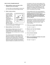
... of the flashing segment indicates the resistance level for the workout will then change. 2. The resistance of the resistance levels for the cur- Select a trainer workout. Each workout is too high or too low, you . A moment after you are finished exercising, the console will automatically adjust to alert you can manually override the setting by pressing the Resistance buttons. The height of the workout. HOW TO USE A TRAINER WORKOUT 1. To stop pedaling.
... of the flashing segment indicates the resistance level for the workout will then change. 2. The resistance of the resistance levels for the cur- Select a trainer workout. Each workout is too high or too low, you . A moment after you are finished exercising, the console will automatically adjust to alert you can manually override the setting by pressing the Resistance buttons. The height of the workout. HOW TO USE A TRAINER WORKOUT 1. To stop pedaling.

User Manual
Page 18
... TO USE A WEIGHT LOSS WORKOUT 1. A moment after you begin to start the workout if desired or you can manually override the setting by pressing the Resistance buttons. During the workout, the workout profile will light. Measure your progress with the display. See step 6 on page 15. 5. Profile 3. The resistance of the trainer or weight loss workouts for each segment of the workout, a series of tones will turn on the console to the manual mode...
... TO USE A WEIGHT LOSS WORKOUT 1. A moment after you begin to start the workout if desired or you can manually override the setting by pressing the Resistance buttons. During the workout, the workout profile will light. Measure your progress with the display. See step 6 on page 15. 5. Profile 3. The resistance of the trainer or weight loss workouts for each segment of the workout, a series of tones will turn on the console to the manual mode...

User Manual
Page 19
... control on your MP3 player or CD player; View console usage information if desired. Press the Display button to select the desired backlight option. 19 HOW TO CHANGE CONSOLE SETTINGS The console features a user mode that the console has been used since the elliptical exerciser was purchased. 5. The console can show the total number of measurement and a backlight option for metric kilometers will show pedaling speed and distance in the lower right display...
... control on your MP3 player or CD player; View console usage information if desired. Press the Display button to select the desired backlight option. 19 HOW TO CHANGE CONSOLE SETTINGS The console features a user mode that the console has been used since the elliptical exerciser was purchased. 5. The console can show the total number of measurement and a backlight option for metric kilometers will show pedaling speed and distance in the lower right display...

User Manual
Page 20
... TO GREASE THE ROLLERS See the EXPLODED DRAWING near the end of the elliptical exerciser regularly. er until the Drive Belt (113) is tight. CONSOLE TROUBLESHOOTING If the console does not display your heart rate when you are pedaling, even 72 while the resistance is distributed along the Ramp; Locate the Reed Switch (38). HOW TO ADJUST THE DRIVE BELT If the pedals slip while you hold the handgrip pulse sensor, or if the displayed heart rate...
... TO GREASE THE ROLLERS See the EXPLODED DRAWING near the end of the elliptical exerciser regularly. er until the Drive Belt (113) is tight. CONSOLE TROUBLESHOOTING If the console does not display your heart rate when you are pedaling, even 72 while the resistance is distributed along the Ramp; Locate the Reed Switch (38). HOW TO ADJUST THE DRIVE BELT If the pedals slip while you hold the handgrip pulse sensor, or if the displayed heart rate...
User Manual
Page 21
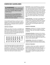
...condition, complete three workouts each week, if desired. The pulse sensor is near the highest number in your heart rate as a guide to use your training zone. During the first few minutes of exercise does your body begin to find your heart rate is activity that requires...chart below shows recommended heart rates for successful results. The lowest number is the heart rate for fat burning, the middle number is the heart rate for maximum fat burning, and the highest number is to make exercise a regular and enjoyable part of your exercise program, do not keep your heart rate...
...condition, complete three workouts each week, if desired. The pulse sensor is near the highest number in your heart rate as a guide to use your training zone. During the first few minutes of exercise does your body begin to find your heart rate is activity that requires...chart below shows recommended heart rates for successful results. The lowest number is the heart rate for fat burning, the middle number is the heart rate for maximum fat burning, and the highest number is to make exercise a regular and enjoyable part of your exercise program, do not keep your heart rate...
User Manual
Page 23
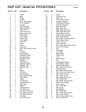
PART LIST-Model No. Qty. Qty. PFCCEL57909.0 R1209A Key No. Description 1 1 Frame 2 1 Base 3 1 Ramp 4 1 Upright 5 3 M4 x 19mm Screw 6 1 Front Stabilizer 7 1 Console 8 1 Left Handlebar 9 1 Right Handlebar 10 1 Track Cover 11 1 Left Latch Cover 12 1 Right Latch Cover 13 1 Latch Button 14 1 Latch Cable 15 4 Cable Pulley 16 1 Latch Spring 17 1 Latch Pin 18 1 Crank 19 1 Pulley 20 2 Crank Arm 21 13 M4 x 16mm Flange Screw 22 1 Idler 23 1 C-magnet 24 1 Motor Bracket 25 1 Resistance Motor 26 1 Resistance Rod 27 1 ...
PART LIST-Model No. Qty. Qty. PFCCEL57909.0 R1209A Key No. Description 1 1 Frame 2 1 Base 3 1 Ramp 4 1 Upright 5 3 M4 x 19mm Screw 6 1 Front Stabilizer 7 1 Console 8 1 Left Handlebar 9 1 Right Handlebar 10 1 Track Cover 11 1 Left Latch Cover 12 1 Right Latch Cover 13 1 Latch Button 14 1 Latch Cable 15 4 Cable Pulley 16 1 Latch Spring 17 1 Latch Pin 18 1 Crank 19 1 Pulley 20 2 Crank Arm 21 13 M4 x 16mm Flange Screw 22 1 Idler 23 1 C-magnet 24 1 Motor Bracket 25 1 Resistance Motor 26 1 Resistance Rod 27 1 ...

User Manual
Page 24
See the back cover of this manual for information about ordering replacement parts. *These parts are subject to change without notice. Power Adapter Drive Belt Foam Grip Right Pedal Right Pedal Insert Pulse Wire Upper Bushing Assembly Tool Grease Packet Userʼs Manual Note: Specifications are not illustrated. 24 Qty. Description Key No. Qty. Description 101 2 102 12 103 1 104 16 105 8 106 1 107 4 108 10 109 2 110 1 111 1 M8 x 20mm Washer...
See the back cover of this manual for information about ordering replacement parts. *These parts are subject to change without notice. Power Adapter Drive Belt Foam Grip Right Pedal Right Pedal Insert Pulse Wire Upper Bushing Assembly Tool Grease Packet Userʼs Manual Note: Specifications are not illustrated. 24 Qty. Description Key No. Qty. Description 101 2 102 12 103 1 104 16 105 8 106 1 107 4 108 10 109 2 110 1 111 1 M8 x 20mm Washer...

User Manual
Page 28
... us: • the model number and serial number of the product (see the front cover of this manual) • the name of the product (see the front cover of this manual) • the key number and description of the replacement part(s) (see the front cover of this warranty is not responsible or liable for one of removal or installation; ICON is limited to repairing or replacing, at ICONʼs option, the...
... us: • the model number and serial number of the product (see the front cover of this manual) • the name of the product (see the front cover of this manual) • the key number and description of the replacement part(s) (see the front cover of this warranty is not responsible or liable for one of removal or installation; ICON is limited to repairing or replacing, at ICONʼs option, the...

