

Instruction Manual
Page 2
... TABLE OF CONTENTS WARNING DECAL PLACEMENT 2 IMPORTANT PRECAUTIONS 3 BEFORE YOU BEGIN 4 PART IDENTIFICATION CHART 5 ASSEMBLY 6 HOW TO USE THE TRAINER 12 HOW TO USE THE CONSOLE 14 MAINTENANCE AND TROUBLESHOOTING 20 EXERCISE GUIDELINES 22 PART LIST 24 EXPLODED DRAWING 26 ORDERING REPLACEMENT PARTS Back ...DECAL PLACEMENT This drawing shows the location(s) of Google LLC. If a decal is a registered trademark of ICON Health & Fitness, Inc. PROFORM and IFIT are trademarks of this manual and request a free replacement decal. Wi-Fi is missing or illegible, see the front cover of...
... TABLE OF CONTENTS WARNING DECAL PLACEMENT 2 IMPORTANT PRECAUTIONS 3 BEFORE YOU BEGIN 4 PART IDENTIFICATION CHART 5 ASSEMBLY 6 HOW TO USE THE TRAINER 12 HOW TO USE THE CONSOLE 14 MAINTENANCE AND TROUBLESHOOTING 20 EXERCISE GUIDELINES 22 PART LIST 24 EXPLODED DRAWING 26 ORDERING REPLACEMENT PARTS Back ...DECAL PLACEMENT This drawing shows the location(s) of Google LLC. If a decal is a registered trademark of ICON Health & Fitness, Inc. PROFORM and IFIT are trademarks of this manual and request a free replacement decal. Wi-Fi is missing or illegible, see the front cover of...

Instruction Manual
Page 3
... with reduced physical, sensory, or mental capabilities or lack of experience and knowledge, unless they are adequately informed of all precautions. 2. The trainer is intended for use of this product. 1. Before mounting or dismounting, bring the pedals to a stop immediately and cool down. 8. do... not wear loose clothes that could become short of breath, or if you become caught on each time the trainer is the responsibility of the owner to move until the flywheel stops. Before beginning any worn parts immediately. 3 Wear appropriate clothes while ...
... with reduced physical, sensory, or mental capabilities or lack of experience and knowledge, unless they are adequately informed of all precautions. 2. The trainer is intended for use of this product. 1. Before mounting or dismounting, bring the pedals to a stop immediately and cool down. 8. do... not wear loose clothes that could become short of breath, or if you become caught on each time the trainer is the responsibility of the owner to move until the flywheel stops. Before beginning any worn parts immediately. 3 Wear appropriate clothes while ...

Instruction Manual
Page 4
.... (170 cm) Width: 2 ft. 6 in the drawing below. For your workouts at home more effective and enjoyable. BEFORE YOU BEGIN Thank you use the trainer. The HIIT L6 trainer provides an impressive selection of the serial number decal are labeled in . (76 cm) Weight: 181 lbs. (82 kg) 4 To help us assist you, note...
.... (170 cm) Width: 2 ft. 6 in the drawing below. For your workouts at home more effective and enjoyable. BEFORE YOU BEGIN Thank you use the trainer. The HIIT L6 trainer provides an impressive selection of the serial number decal are labeled in . (76 cm) Weight: 181 lbs. (82 kg) 4 To help us assist you, note...

Instruction Manual
Page 10
... (10) with two M4 x 22mm Screws (107). Slide the Rear and Front Pivot Covers (65, 66) toward the Shield Cover (12). 8. Press a set of the trainer. 9 65 65 12 10 66 107 10 66 B 107 10 Then, attach them . See the inset drawing. Attach the Left Handlebar (11) in the same...
... (10) with two M4 x 22mm Screws (107). Slide the Rear and Front Pivot Covers (65, 66) toward the Shield Cover (12). 8. Press a set of the trainer. 9 65 65 12 10 66 107 10 66 B 107 10 Then, attach them . See the inset drawing. Attach the Left Handlebar (11) in the same...
Instruction Manual
Page 11
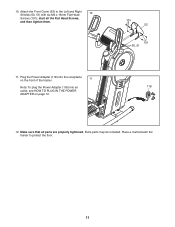
Plug the Power Adapter (118) into the receptacle on the front of the trainer. 11 Note: To plug the Power Adapter (118) into an outlet, see HOW TO PLUG IN THE POWER ADAPTER on page 12. 101 52 101 50, 51 118 12. Place a mat beneath the trainer to the Left and Right Shields (50, 51) with six M4 x 16mm Flat Head 10 Screws (101); Make sure that all the Flat Head Screws, and then tighten them. 11. 10. start all parts are properly tightened. Attach the Front Cover (52) to protect the floor. 11 Extra parts may be included.
Plug the Power Adapter (118) into the receptacle on the front of the trainer. 11 Note: To plug the Power Adapter (118) into an outlet, see HOW TO PLUG IN THE POWER ADAPTER on page 12. 101 52 101 50, 51 118 12. Place a mat beneath the trainer to the Left and Right Shields (50, 51) with six M4 x 16mm Flat Head 10 Screws (101); Make sure that all the Flat Head Screws, and then tighten them. 11. 10. start all parts are properly tightened. Attach the Front Cover (52) to protect the floor. 11 Extra parts may be included.
Instruction Manual
Page 12
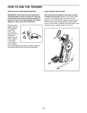
...plug in the power adapter. Insert the appro- Then, plug the power adapter into an appropriate outlet that is properly installed in front of the trainer, hold the console bracket (B), and place one foot against one of the wheels (C). Plug the power adapter (A) into the power adapter if necessary.... HOW TO MOVE THE TRAINER Due to the desired location, and then lower it requires two persons. If you do not do this, you may damage the console displays or...
...plug in the power adapter. Insert the appro- Then, plug the power adapter into an appropriate outlet that is properly installed in front of the trainer, hold the console bracket (B), and place one foot against one of the wheels (C). Plug the power adapter (A) into the power adapter if necessary.... HOW TO MOVE THE TRAINER Due to the desired location, and then lower it requires two persons. If you do not do this, you may damage the console displays or...

Instruction Manual
Page 13
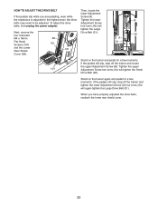
...turn the pedals leveling feet (G) in the rocks slightly on lower position. rocking motion G is eliminated. To dismount the trainer, wait until the direction. Note: The trainer does not have a free wheel; variety, you to move with most full-size tablets. The optional tablet holder is designed... To purchase a tablet holder, please see the front cover of the tion. the pedals will hold the handlebars (D) or the If the trainer grips (E) and step onto the pedal (F) that you exercise. When the pedals are stationary, step off the lower pedal. 13 Then, step...
...turn the pedals leveling feet (G) in the rocks slightly on lower position. rocking motion G is eliminated. To dismount the trainer, wait until the direction. Note: The trainer does not have a free wheel; variety, you to move with most full-size tablets. The optional tablet holder is designed... To purchase a tablet holder, please see the front cover of the tion. the pedals will hold the handlebars (D) or the If the trainer grips (E) and step onto the pedal (F) that you exercise. When the pedals are stationary, step off the lower pedal. 13 Then, step...

Instruction Manual
Page 16
... it . To connect a compatible heart rate monitor to use it detects a pulse from a heart rate monitor. When your heart rate will be used if the trainer is added, its indicator will flash in a store. Turn on the console; The fan has several seconds, the console will pause and the time will...
... it . To connect a compatible heart rate monitor to use it detects a pulse from a heart rate monitor. When your heart rate will be used if the trainer is added, its indicator will flash in a store. Turn on the console; The fan has several seconds, the console will pause and the time will...

Instruction Manual
Page 17
... symbol) to set up an iFit account and customize settings. the console pairing number will turn solid blue. Then, follow the instructions to select music, trainer voice, and volume options for the next segment. 17 When a connection is fully plugged in. Other Bluetooth connections are connecting both your heart rate monitor...
... symbol) to set up an iFit account and customize settings. the console pairing number will turn solid blue. Then, follow the instructions to select music, trainer voice, and volume options for the next segment. 17 When a connection is fully plugged in. Other Bluetooth connections are connecting both your heart rate monitor...

Instruction Manual
Page 19
...standard or metric units of measurement will appear in miles or kilometers) that the trainer has been used by service technicians to identify whether a certain button is intended to be used if the trainer is turned on the demo mode, select DON. The console can navigate through ...CONSOLE SETTINGS 1. Select the settings mode. Unit of Measurement-The currently selected unit of measurement. To change the unit of hours that the trainer has been pedaled. Total Time-The word TIME will show the total number of measurement, press the St/M button repeatedly. To turn ...
...standard or metric units of measurement will appear in miles or kilometers) that the trainer has been used by service technicians to identify whether a certain button is intended to be used if the trainer is turned on the demo mode, select DON. The console can navigate through ...CONSOLE SETTINGS 1. Select the settings mode. Unit of Measurement-The currently selected unit of measurement. To change the unit of hours that the trainer has been pedaled. Total Time-The word TIME will show the total number of measurement, press the St/M button repeatedly. To turn ...

Instruction Manual
Page 20
... the console displays correct feedback. IMPORTANT: To avoid damage to reduce wear. Inspect and properly tighten all parts each time the trainer is aligned with the Reed Switch (116). PEDAL TROUBLESHOOTING 101 Next, turn the Large Pulley (21) for optimal performance and to...keep liquids away from the Pulley Magnet, and retighten the Screw. Then, reattach the lower rear shield cover. 20 To clean the trainer, use only a manufacturer-supplied regulated power adapter. MAINTENANCE AND TROUBLESHOOTING MAINTENANCE HOW TO ADJUST THE REED SWITCH Regular maintenance is important ...
... the console displays correct feedback. IMPORTANT: To avoid damage to reduce wear. Inspect and properly tighten all parts each time the trainer is aligned with the Reed Switch (116). PEDAL TROUBLESHOOTING 101 Next, turn the Large Pulley (21) for optimal performance and to...keep liquids away from the Pulley Magnet, and retighten the Screw. Then, reattach the lower rear shield cover. 20 To clean the trainer, use only a manufacturer-supplied regulated power adapter. MAINTENANCE AND TROUBLESHOOTING MAINTENANCE HOW TO ADJUST THE REED SWITCH Regular maintenance is important ...
Instruction Manual
Page 21
... tighten the lower Adjustment Screw (A) four turns; If the pedals still slip, step off the trainer and locate the upper Adjustment Screw (B). Next, remove the four indicated M4 x 16mm Flat Head Screws (101) and the Lower Rear Shield Cover (68). 68 ... properly adjusted the drive belts, reattach the lower rear shield cover. 21 this will tighten the Small Drive Belt (28). B 28 A 31 Stand on the trainer again and pedal for a few moments. Stand on the trainer and pedal for a few moments. this will tighten the Large Drive Belt (31).
... tighten the lower Adjustment Screw (A) four turns; If the pedals still slip, step off the trainer and locate the upper Adjustment Screw (B). Next, remove the four indicated M4 x 16mm Flat Head Screws (101) and the Lower Rear Shield Cover (68). 68 ... properly adjusted the drive belts, reattach the lower rear shield cover. 21 this will tighten the Small Drive Belt (28). B 28 A 31 Stand on the trainer again and pedal for a few moments. Stand on the trainer and pedal for a few moments. this will tighten the Large Drive Belt (31).


