
English Manual
Page 2
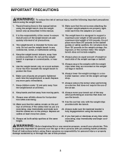
... 1-800-999-3756, Monday through Friday, 6 a.m. WARNING DECAL PLACEMENT The warning decals shown here have been placed on the weight bench in the location shown. 2 Place the decal on the weight bench in the center of this manual. Mountain Time, and order a free replacement decal. If a decal is attached in the locations shown.
... 1-800-999-3756, Monday through Friday, 6 a.m. WARNING DECAL PLACEMENT The warning decals shown here have been placed on the weight bench in the location shown. 2 Place the decal on the weight bench in the center of this manual. Mountain Time, and order a free replacement decal. If a decal is attached in the locations shown.
English Manual
Page 3
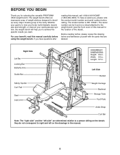
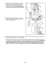
...Make sure that does not use the weight bench in any exercise program, consult your bench out of the way when performing an exercise that the cables remain on the pulleys at least every two years. 11. Always set screws attaching the Olympic weight adapters are exercising, stop ...immediately and begin cooling down. Keep the weight bench indoors, away from moving parts. 9. Note: The weight bench does not include weights. 14. If the cables bind as described...
...Make sure that does not use the weight bench in any exercise program, consult your bench out of the way when performing an exercise that the cables remain on the pulleys at least every two years. 11. Always set screws attaching the Olympic weight adapters are exercising, stop ...immediately and begin cooling down. Keep the weight bench indoors, away from moving parts. 9. Note: The weight bench does not include weights. 14. If the cables bind as described...
English Manual
Page 4
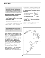
BEFORE YOU BEGIN Thank you for the location of the body. If you want. The serial number can be found on a decal attached to tone your body, build dramatic muscle size and strength, or improve your benefit, read this manual carefully before calling. Length: 97 in...with the parts that are determined relative to achieve the specific results you have questions after reading this manual for selecting the versatile PROFORM® C840 weight bench. Left Side Barbell Safety Spotter Curl Pad Seat Leg Lever Weight Carriage Backrest Storage Tube Foot Plate Ankle Strap Curl Bar Note: ...
BEFORE YOU BEGIN Thank you for the location of the body. If you want. The serial number can be found on a decal attached to tone your body, build dramatic muscle size and strength, or improve your benefit, read this manual carefully before calling. Length: 97 in...with the parts that are determined relative to achieve the specific results you have questions after reading this manual for selecting the versatile PROFORM® C840 weight bench. Left Side Barbell Safety Spotter Curl Pad Seat Leg Lever Weight Carriage Backrest Storage Tube Foot Plate Ankle Strap Curl Bar Note: ...
English Manual
Page 5
...help identifying small parts, use the PART IDENTIFICATION CHART. • Tighten all parts are required for Yourself This manual is completed. Attach another Base Cap to the Bench Frame (1) with two M10 x 68mm Bolts (113), two M10 Washers (99), and two M10 Nylon Locknuts (97). 111...1. Before beginning assembly, carefully read the following tools (not included) are oriented as grease or petroleum jelly, and soapy water. Attach the Bench Leg (3) to the Bench Frame with two M10 x 2 68mm Bolts (113), two M10 Washers (99), and two M10 Nylon Locknuts. Before beginning, make...
...help identifying small parts, use the PART IDENTIFICATION CHART. • Tighten all parts are required for Yourself This manual is completed. Attach another Base Cap to the Bench Frame (1) with two M10 x 68mm Bolts (113), two M10 Washers (99), and two M10 Nylon Locknuts (97). 111...1. Before beginning assembly, carefully read the following tools (not included) are oriented as grease or petroleum jelly, and soapy water. Attach the Bench Leg (3) to the Bench Frame with two M10 x 2 68mm Bolts (113), two M10 Washers (99), and two M10 Nylon Locknuts. Before beginning, make...
English Manual
Page 6
... two M10 Nylon Locknuts (97). the Leg Lever must be able to the Bench 3 Frame (1) with grease. Do not overtighten the Screw. 1 97 11 27 Lubricate 110 5. Make sure the Backrest Tubes are closer to pivot easily. Attach the Backrest Bracket (7) to the Leg Lever (4) with four M10 x 45mm...Tubes (8) with an M8 x 58mm Bolt (106), two M8 Washers (100), a 10mm Spacer (30), and an M8 Nylon Locknut (96). Attach the Leg Lever (4) to the Bench Frame (1) with the Bolt and an M10 Nylon Locknut (97). Do not overtighten the Locknut; Lubricate an M10 x 78mm Bolt (110) with grease...
... two M10 Nylon Locknuts (97). the Leg Lever must be able to the Bench 3 Frame (1) with grease. Do not overtighten the Screw. 1 97 11 27 Lubricate 110 5. Make sure the Backrest Tubes are closer to pivot easily. Attach the Backrest Bracket (7) to the Leg Lever (4) with four M10 x 45mm...Tubes (8) with an M8 x 58mm Bolt (106), two M8 Washers (100), a 10mm Spacer (30), and an M8 Nylon Locknut (96). Attach the Leg Lever (4) to the Bench Frame (1) with the Bolt and an M10 Nylon Locknut (97). Do not overtighten the Locknut; Lubricate an M10 x 78mm Bolt (110) with grease...
English Manual
Page 7
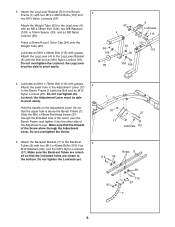
...(97). Tighten the four M10 Nylon Locknuts (97) used in the Bench Frame (1) and under the Backrest Bracket arm. Make sure that the M10 x 62mm Flat Head Screw (27) is under the Adjustment Lever (11). Attach the Backrest Tubes (8) to pivot easily. 7. the Backrest Tubes must ...be able to the Bench Frame (1) with grease. Insert the Backrest Bracket (7) through the slot in steps 1 and 5. 6 97 99 8 ...
...(97). Tighten the four M10 Nylon Locknuts (97) used in the Bench Frame (1) and under the Backrest Bracket arm. Make sure that the M10 x 62mm Flat Head Screw (27) is under the Adjustment Lever (11). Attach the Backrest Tubes (8) to pivot easily. 7. the Backrest Tubes must ...be able to the Bench Frame (1) with grease. Insert the Backrest Bracket (7) through the slot in steps 1 and 5. 6 97 99 8 ...
English Manual
Page 8
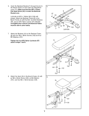
... Pad Tube as shown. 9. Wet both sides of the Pad Tube with 10 two M6 x 16mm Screws (104). 16 10 18 17 19 19 11. Attach the Right Upright (69), which has numbers on the indicated side, to the Rack Foot (46) with an M10 x 50mm Screw (108) and an M10... Washer (99). Attach a Guide Bar (41) to the Curl Post (6) with soapy water. Attach the Curl Pad (16) to the Rack Foot (46) with two M10 x 68mm Bolts (113), four M10 Washers (99), and...
... Pad Tube as shown. 9. Wet both sides of the Pad Tube with 10 two M6 x 16mm Screws (104). 16 10 18 17 19 19 11. Attach the Right Upright (69), which has numbers on the indicated side, to the Rack Foot (46) with an M10 x 50mm Screw (108) and an M10... Washer (99). Attach a Guide Bar (41) to the Curl Post (6) with soapy water. Attach the Curl Pad (16) to the Rack Foot (46) with two M10 x 68mm Bolts (113), four M10 Washers (99), and...

English Manual
Page 9
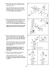
... (35) with three M10 x 68mm Bolts (113), three M10 Washers (99), and two M10 Nylon Locknuts (97). Attach the Foot Plate to the Center Base (32) 14 with two M10 x 92mm Carriage Bolts (111) and two M10 Nylon...yet. 98 107 32 110 33 Set the Center Base (32) inside of the plate is oriented as shown. Attach the Left Base (35) to the Center Base with two M10 x 78mm Bolts (110), two M10 Washers (99... the Rear Base (33) with an M4 x 16mm Screw (107) and an M8 x 16mm Screw (98). 117 33 Attach the Rear Base (33) to the Center Base (32) with two M10 x 68mm Bolts (113), two M10 99 Washers...
... (35) with three M10 x 68mm Bolts (113), three M10 Washers (99), and two M10 Nylon Locknuts (97). Attach the Foot Plate to the Center Base (32) 14 with two M10 x 92mm Carriage Bolts (111) and two M10 Nylon...yet. 98 107 32 110 33 Set the Center Base (32) inside of the plate is oriented as shown. Attach the Left Base (35) to the Center Base with two M10 x 78mm Bolts (110), two M10 Washers (99... the Rear Base (33) with an M4 x 16mm Screw (107) and an M8 x 16mm Screw (98). 117 33 Attach the Rear Base (33) to the Center Base (32) with two M10 x 68mm Bolts (113), two M10 99 Washers...
English Manual
Page 10
..., tap the left Rack Foot (46) into an adjustment hole near the bottom of the screw holes. Attach the other Rack Foot (not shown) to a Safety Spotter (52) with two M10 x 68mm Bolts ...handle. Identify the Left and Right Barbell Gliders (51, 123) by the position of the Right Upright (69). Attach the Right Spotter Hook (53) to the Right Base (not shown) in the same manner. Always set both...118). Do not tighten the Locknuts yet. 15 113 99 113 99 34 47 97 118 107 32 97 16. Attach the Rack Foot to the Right Base (34) with three M10 x 68mm Bolts (113), three M10 Washers (99),...
..., tap the left Rack Foot (46) into an adjustment hole near the bottom of the screw holes. Attach the other Rack Foot (not shown) to a Safety Spotter (52) with two M10 x 68mm Bolts ...handle. Identify the Left and Right Barbell Gliders (51, 123) by the position of the Right Upright (69). Attach the Right Spotter Hook (53) to the Right Base (not shown) in the same manner. Always set both...118). Do not tighten the Locknuts yet. 15 113 99 113 99 34 47 97 118 107 32 97 16. Attach the Rack Foot to the Right Base (34) with three M10 x 68mm Bolts (113), three M10 Washers (99),...
English Manual
Page 11
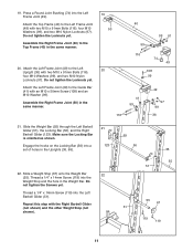
... to the Left Upright (36) with an M10 x 50mm Screw (108) and an M10 Washer (99). Attach the Left Frame Joint (49) to the Top Frame (40) in the Uprights (36, 69). 36 22. Do ...not tighten the Locknuts yet. Attach the Left Frame Joint (49) to the Left Frame Joint (49) with the Right Barbell Glider (not ...(119) into the Left Frame Joint (49). 19. Press a Round Joint Bushing (74) into the Left Barbell Glider (51). Attach the Top Frame (40) to the Guide Bar (41) with two M10 x 91mm Bolts (116), four M10 Washers (99), and...
... to the Left Upright (36) with an M10 x 50mm Screw (108) and an M10 Washer (99). Attach the Left Frame Joint (49) to the Top Frame (40) in the Uprights (36, 69). 36 22. Do ...not tighten the Locknuts yet. Attach the Left Frame Joint (49) to the Left Frame Joint (49) with the Right Barbell Glider (not ...(119) into the Left Frame Joint (49). 19. Press a Round Joint Bushing (74) into the Left Barbell Glider (51). Attach the Top Frame (40) to the Guide Bar (41) with two M10 x 91mm Bolts (116), four M10 Washers (99), and...
English Manual
Page 12
... Carriage Stop (70) to the Center Base (32) and Rear Base (33) with an M10 x 88mm Bolt (114) and an M10 Nylon Locknut (97). Attach the Rear Upright (38), with two M10 x 75mm Bolts (127), four M10 Washers (99), and two M10 Nylon Locknuts (97). 23. Do not tighten the ...Screw yet. Attach the Center Upright (37) to the Rear Upright (38), at the indicated hole, with an M10 x 78mm Bolt (110), an M10 Washer (99), and an...
... Carriage Stop (70) to the Center Base (32) and Rear Base (33) with an M10 x 88mm Bolt (114) and an M10 Nylon Locknut (97). Attach the Rear Upright (38), with two M10 x 75mm Bolts (127), four M10 Washers (99), and two M10 Nylon Locknuts (97). 23. Do not tighten the ...Screw yet. Attach the Center Upright (37) to the Rear Upright (38), at the indicated hole, with an M10 x 78mm Bolt (110), an M10 Washer (99), and an...
English Manual
Page 13
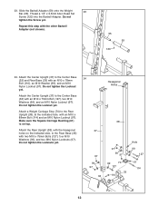
... Locknuts yet. 65 97 70 114 61 132 71 Hole 38 39 97 99 99 130 38 27. Attach the Rear Top Frame (39) to the Rear Upright (38) with an M10 x 88mm Bolt (114) and an M10 ...Nylon Locknut (97). Attach the Rear Top Frame (39) to the Rear Upright (38), at the indicated hole, with two M10 x 72mm Hex ...38). Do not tighten the Locknuts yet. 27 110 126 40 99 99 39 97 99 97 37 99 97 13 25. Attach the Weight Carriage Stop (70) to the Top Frame (40) with two M10 x 78mm Bolts (110), two M10 Washers ...
... Locknuts yet. 65 97 70 114 61 132 71 Hole 38 39 97 99 99 130 38 27. Attach the Rear Top Frame (39) to the Rear Upright (38) with an M10 x 88mm Bolt (114) and an M10 ...Nylon Locknut (97). Attach the Rear Top Frame (39) to the Rear Upright (38), at the indicated hole, with two M10 x 72mm Hex ...38). Do not tighten the Locknuts yet. 27 110 126 40 99 99 39 97 99 97 37 99 97 13 25. Attach the Weight Carriage Stop (70) to the Top Frame (40) with two M10 x 78mm Bolts (110), two M10 Washers ...
English Manual
Page 14
... steps 11-28. Tap the 25mm Round Outer Cap (94) onto the right axle on the Butterfly Frame (42). Attach the Left Fly Arm (44) in the inset drawing. Tighten the 1/4" x 14mm Screws (119) used in step ...Allen Head Set Screws (120) used in step 23. 110 99 99 39 37 97 97 42 29. Attach the Cable to verify cable routing. Do not tighten the Locknuts yet. Have another person slide the Right Fly... with grease. Note: Be careful not to the Rear Top 28 Frame (39) with the Right Fly Arm. Attach the Butterfly Frame (42) to confuse the Left Fly Arm (44) with two M10 x 78mm Bolts (110),...
... steps 11-28. Tap the 25mm Round Outer Cap (94) onto the right axle on the Butterfly Frame (42). Attach the Left Fly Arm (44) in the inset drawing. Tighten the 1/4" x 14mm Screws (119) used in step ...Allen Head Set Screws (120) used in step 23. 110 99 99 39 37 97 97 42 29. Attach the Cable to verify cable routing. Do not tighten the Locknuts yet. Have another person slide the Right Fly... with grease. Note: Be careful not to the Rear Top 28 Frame (39) with the Right Fly Arm. Attach the Butterfly Frame (42) to confuse the Left Fly Arm (44) with two M10 x 78mm Bolts (110),...

English Manual
Page 15
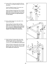
... "V"-pulley and a Large Cable Trap (88) to the Right Fly Arm (43) with an M10 x 60mm Bolt (128) and an M10 Nylon Locknut (97). Attach the Pulley to the Center Upright (37) with an M10 x 45mm Bolt (112) and an M10 Nylon Locknut (97). 33. bracket (73) with an M10 x ... (90). Make sure the Cable Trap is oriented to hold the Cable in the groove of the "V"-pulley. 37 97 89 88 128 83 32. Attach the "V"-pulley and a Large Cable Trap (88) to the Double "U"- 31. Wrap the Butterfly Cable (83) over a "V"-pulley 33 (89). Make sure the Cable Trap...
... "V"-pulley and a Large Cable Trap (88) to the Right Fly Arm (43) with an M10 x 60mm Bolt (128) and an M10 Nylon Locknut (97). Attach the Pulley to the Center Upright (37) with an M10 x 45mm Bolt (112) and an M10 Nylon Locknut (97). 33. bracket (73) with an M10 x ... (90). Make sure the Cable Trap is oriented to hold the Cable in the groove of the "V"-pulley. 37 97 89 88 128 83 32. Attach the "V"-pulley and a Large Cable Trap (88) to the Double "U"- 31. Wrap the Butterfly Cable (83) over a "V"-pulley 33 (89). Make sure the Cable Trap...

English Manual
Page 16
...81) over a 90mm Pulley (90) and down through the Rear Top Frame (39) and over a 90mm Pulley (90). Attach the Lat Cable (81) to the indicated hole in the two Pulley Plates (72) with an M10 x 78mm Bolt (110...), two M10 Washers (99), two 17mm Spacers (86), and an M10 Nylon Locknut (97). 36. Attach the Pulley inside the Rear Top Frame with an M10 Nylon Locknut (97). Make sure the Cable Trap is turned ...110) and an M10 Nylon Locknut (97). 81 97 125 72 112 90 72 39 90 97 110 81 39. Attach the Pulley and a Small Cable Trap (125) to the M10 x 19mm Hex 39 Head Bolt (132) in ...
...81) over a 90mm Pulley (90) and down through the Rear Top Frame (39) and over a 90mm Pulley (90). Attach the Lat Cable (81) to the indicated hole in the two Pulley Plates (72) with an M10 x 78mm Bolt (110...), two M10 Washers (99), two 17mm Spacers (86), and an M10 Nylon Locknut (97). 36. Attach the Pulley inside the Rear Top Frame with an M10 Nylon Locknut (97). Make sure the Cable Trap is turned ...110) and an M10 Nylon Locknut (97). 81 97 125 72 112 90 72 39 90 97 110 81 39. Attach the Pulley and a Small Cable Trap (125) to the M10 x 19mm Hex 39 Head Bolt (132) in ...

English Manual
Page 17
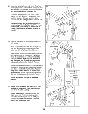
... an M10 x 45mm Bolt (112) and an M10 Nylon Locknut (97). 42. Attach the Pulley to hold the Cable in the groove of the Pulley. 112 97 90 72... shown. Route the Low Cable (82) over a 90mm Pulley 41 (90) as shown. Locate the Low Cable (82). Attach the Pulley to the second set of holes from the bottom of the Cable through the Center Upright (37) and under a ...90mm Pulley 42 (90) as shown. Attach the Pulley and a Cable Trap (125) to the Double "U"-bracket (73) with an M10 x 75mm Bolt (127), two...
... an M10 x 45mm Bolt (112) and an M10 Nylon Locknut (97). 42. Attach the Pulley to hold the Cable in the groove of the Pulley. 112 97 90 72... shown. Route the Low Cable (82) over a 90mm Pulley 41 (90) as shown. Locate the Low Cable (82). Attach the Pulley to the second set of holes from the bottom of the Cable through the Center Upright (37) and under a ...90mm Pulley 42 (90) as shown. Attach the Pulley and a Cable Trap (125) to the Double "U"-bracket (73) with an M10 x 75mm Bolt (127), two...
English Manual
Page 18
... x 75mm Bolt (127), two M10 Washers (99), two 27mm Spacers (87), and an M10 Nylon Locknut (97). Attach the Butterfly Backrest (80) to pivot easily. 97 99 87 33 82 87 127 99 45. Attach the Low Cable (82) inside the Rear Base 44 (33) with two M6 x 72mm Screws (105) and... page 22 of the cables does not move smoothly over the pulleys. If one of this manual for proper cable routing. Before using the weight bench, pull each cable a few times to remove it by tightening the cables. If there is used. See the CABLE DIAGRAMS on page 23. 18 Do...
... x 75mm Bolt (127), two M10 Washers (99), two 27mm Spacers (87), and an M10 Nylon Locknut (97). Attach the Butterfly Backrest (80) to pivot easily. 97 99 87 33 82 87 127 99 45. Attach the Low Cable (82) inside the Rear Base 44 (33) with two M6 x 72mm Screws (105) and... page 22 of the cables does not move smoothly over the pulleys. If one of this manual for proper cable routing. Before using the weight bench, pull each cable a few times to remove it by tightening the cables. If there is used. See the CABLE DIAGRAMS on page 23. 18 Do...
English Manual
Page 19
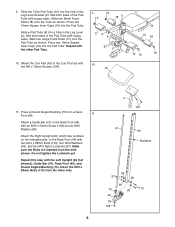
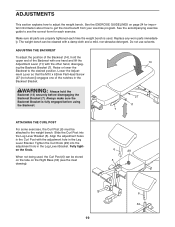
... the position of the Backrest (14), hold the Backrest (14) securely before using the Backrest. 27 11 7 ATTACHING THE CURL POST For some exercises, the Curl Post (6) must be attached to the desired position. WARNING: Always hold the upper end of the notches in the Curl Post with the other...Always make sure the Backrest Bracket is used , the Curl Post (6) can be stored on the tube on page 24 for each time the weight bench is fully engaged before disengaging the Backrest Bracket (7). When not being used . See the EXERCISE GUIDELINES on the Right Base (34) (see the correct...
... the position of the Backrest (14), hold the Backrest (14) securely before using the Backrest. 27 11 7 ATTACHING THE CURL POST For some exercises, the Curl Post (6) must be attached to the desired position. WARNING: Always hold the upper end of the notches in the Curl Post with the other...Always make sure the Backrest Bracket is used , the Curl Post (6) can be stored on the tube on page 24 for each time the weight bench is fully engaged before disengaging the Backrest Bracket (7). When not being used . See the EXERCISE GUIDELINES on the Right Base (34) (see the correct...
English Manual
Page 20
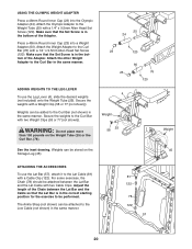
...stored on the Weight Tube (25) or the Curl Bar. (76). For some exercises, the Chain (78) should be attached to the Weight Tube (25) with two Weight Clips (53 or 77 [not shown]). The Ankle Strap (not shown) ...the weights to the Curl Bar in the same manner. 81 122 78 122 57 20 Weights can be attached between the Lat Bar and the Cable so that the Set Screw is in the same manner. ADDING WEIGHTS... TO THE LEG LEVER To use the Lat Bar (57), attach it to the Curl Bar (not shown) in the bottom of the Chain between the Lat Bar and the...
...stored on the Weight Tube (25) or the Curl Bar. (76). For some exercises, the Chain (78) should be attached to the Weight Tube (25) with two Weight Clips (53 or 77 [not shown]). The Ankle Strap (not shown) ...the weights to the Curl Bar in the same manner. 81 122 78 122 57 20 Weights can be attached between the Lat Bar and the Cable so that the Set Screw is in the same manner. ADDING WEIGHTS... TO THE LEG LEVER To use the Lat Bar (57), attach it to the Curl Bar (not shown) in the bottom of the Chain between the Lat Bar and the...
English Manual
Page 28
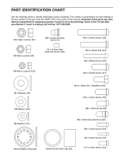
... x 16mm Screw (107) 25mm Round Outer Cap (94) 1/4" x 14mm Screw (119) PART IDENTIFICATION CHART See the drawings below to see if it has been pre-attached. If a part is not in the parts bag, check to identify small parts used in the center of the part, from the PART LIST in...
... x 16mm Screw (107) 25mm Round Outer Cap (94) 1/4" x 14mm Screw (119) PART IDENTIFICATION CHART See the drawings below to see if it has been pre-attached. If a part is not in the parts bag, check to identify small parts used in the center of the part, from the PART LIST in...


