
Owners Manual
Page 1
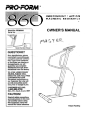
ual carefully before using this manual for future reference. Pi2O•FORM INDEPENDENT 4 ACTION MAGNETIC RESISTANCE Model No. As a manufacturer, weare committed to you. Save this equipment. OWNER'S MANUAL Serial Number Decal QUESTIONS? MST CAUTION! TO AVOID UNNECESSARY DELAYS, PLEASE CALL DIRECT TO OUR TOLL-FREE CUSTOMER HOT LINE. Patent Pending CUSTOMER HOT LINE: 1-800-999-3756 Mon.-Fri., 6 a.m.-6 p.m. If you have...
ual carefully before using this manual for future reference. Pi2O•FORM INDEPENDENT 4 ACTION MAGNETIC RESISTANCE Model No. As a manufacturer, weare committed to you. Save this equipment. OWNER'S MANUAL Serial Number Decal QUESTIONS? MST CAUTION! TO AVOID UNNECESSARY DELAYS, PLEASE CALL DIRECT TO OUR TOLL-FREE CUSTOMER HOT LINE. Patent Pending CUSTOMER HOT LINE: 1-800-999-3756 Mon.-Fri., 6 a.m.-6 p.m. If you have...
Owners Manual
Page 2
... product. Keep your physician. This is in this manual. Use the stepper only as described in use of this or any worn parts Immediately. 3. TABLE OF CONTENTS IMPORTANT SAFETY PRECAUTIONS BEFORE YOU BEGIN ASSEMBLY OPERATION CONDITIONING GUIDELINES TROUBLE-SHOOTING AND MAINTENANCE PART LIST EXPLODED DRAWING ORDERING REPLACEMENT PARTS LIMITED WARRANTY 2 3 4 5 7 8 10 11 Back Cover Back Cover IMPORTANT SAFETY PRECAUTIONS WARNING: To reduce the risk of...
... product. Keep your physician. This is in this manual. Use the stepper only as described in use of this or any worn parts Immediately. 3. TABLE OF CONTENTS IMPORTANT SAFETY PRECAUTIONS BEFORE YOU BEGIN ASSEMBLY OPERATION CONDITIONING GUIDELINES TROUBLE-SHOOTING AND MAINTENANCE PART LIST EXPLODED DRAWING ORDERING REPLACEMENT PARTS LIMITED WARRANTY 2 3 4 5 7 8 10 11 Back Cover Back Cover IMPORTANT SAFETY PRECAUTIONS WARNING: To reduce the risk of...
Owners Manual
Page 3
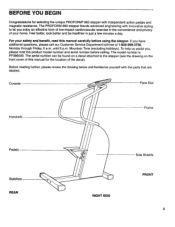
... our Customer Service Department toll-free at 1-800-999-3756, Monday through Friday, 6 a.m. The serial number can be healthier in the convenience and privacy of the decal). Mountain Time (excluding holidays). If you , please note the product model number and serial number before using the stepper. Console Pace Dial Handrails Frame Pedals Stabilizer REAR RIGHT SIDE Side Shields FRONT 3 The PROFORM 860 stepper blends...
... our Customer Service Department toll-free at 1-800-999-3756, Monday through Friday, 6 a.m. The serial number can be healthier in the convenience and privacy of the decal). Mountain Time (excluding holidays). If you , please note the product model number and serial number before using the stepper. Console Pace Dial Handrails Frame Pedals Stabilizer REAR RIGHT SIDE Side Shields FRONT 3 The PROFORM 860 stepper blends...
Owners Manual
Page 4
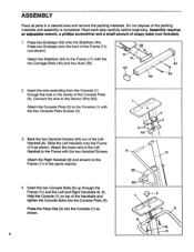
... 5 .--%-- 9 / 8 1. ) 6 11 Do not dispose of the Left Handrail (8). Assembly requires an adjustable wrench, a phillips screwdriver and a small amount of the Frame (11) (not shown). ASSEMBLY Place all parts in a cleared area and remove the packing materials. Attach the lower end of the Handrails and tighten the Console Bolts into the Console (1) as shown. Press two Endcaps onto the front of soapy water...
... 5 .--%-- 9 / 8 1. ) 6 11 Do not dispose of the Left Handrail (8). Assembly requires an adjustable wrench, a phillips screwdriver and a small amount of the Frame (11) (not shown). ASSEMBLY Place all parts in a cleared area and remove the packing materials. Attach the lower end of the Handrails and tighten the Console Bolts into the Console (1) as shown. Press two Endcaps onto the front of soapy water...
Owners Manual
Page 5
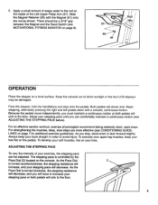
... the Pace Dial is controlled by the Pace Dial (2) located on the console. Always keep your feet flat on the inside of your toes. ADJUSTING THE STEPPING PACE To vary the intensity of the Left Upper Pedal Arm (57). There should be a 3/16" gap between the Magnet and the Reed Switch (see MOTIVATIONAL FITNESS MONITOR on your exercise, the stepping pace can comfortably...
... the Pace Dial is controlled by the Pace Dial (2) located on the console. Always keep your feet flat on the inside of your toes. ADJUSTING THE STEPPING PACE To vary the intensity of the Left Upper Pedal Arm (57). There should be a 3/16" gap between the Magnet and the Reed Switch (see MOTIVATIONAL FITNESS MONITOR on your exercise, the stepping pace can comfortably...
Owners Manual
Page 6
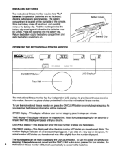
... power off as shown, and carefully remove the battery clip. If the pedals are not moved and the ON/CLEAR button is not pressed for ten seconds or longer, the TIME display will turn the motivational fitness monitor on the right side of the console. TIME display-This display will show the elapsed time. Note: The number displayed is located on , press the ON/CLEAR button or simply begin stepping...
... power off as shown, and carefully remove the battery clip. If the pedals are not moved and the ON/CLEAR button is not pressed for ten seconds or longer, the TIME display will turn the motivational fitness monitor on the right side of the console. TIME display-This display will show the elapsed time. Note: The number displayed is located on , press the ON/CLEAR button or simply begin stepping...
Owners Manual
Page 7
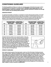
... your heart rate to your training zone as a guide. Remember that proper nutrition and adequate rest are listed for 20 to success is CONSISTENCY. 7 WARNING: Before beginning this or any exercise program, consult your breath. For effective aerobic exercise, your heart rate should consist of stretching to warm up prepares the body for successful results. Training zones are essential for exercise by using your heart rate...
... your heart rate to your training zone as a guide. Remember that proper nutrition and adequate rest are listed for 20 to success is CONSISTENCY. 7 WARNING: Before beginning this or any exercise program, consult your breath. For effective aerobic exercise, your heart rate should consist of stretching to warm up prepares the body for successful results. Training zones are essential for exercise by using your heart rate...
Owners Manual
Page 8
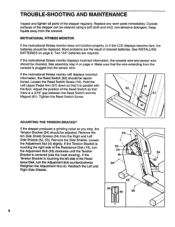
... Tension Bracket is touching the left side of the Resistance Disk (19), turn the Adjustment Bolt counterclockwise. Remove the Side Shields. Keep liquids away from the console. See assembly step 4 on page 6. Outside surfaces of the stepper regularly. See INSTALLING BATTERIES on page 4. Most problems are required. TROUBLE-SHOOTING AND MAINTENANCE Inspect and tighten all parts of the stepper can be checked. Loosen the Reed Switch Screw (10).
... Tension Bracket is touching the left side of the Resistance Disk (19), turn the Adjustment Bolt counterclockwise. Remove the Side Shields. Keep liquids away from the console. See assembly step 4 on page 6. Outside surfaces of the stepper regularly. See INSTALLING BATTERIES on page 4. Most problems are required. TROUBLE-SHOOTING AND MAINTENANCE Inspect and tighten all parts of the stepper can be checked. Loosen the Reed Switch Screw (10).
Owners Manual
Page 9
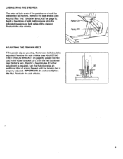
... 0 9 LUBRICATING THE STEPPER The axles at both sides of the stepper. Apply a few minutes. Remove the side shields (see ADJUSTING THE TENSION BRACKET on both ends of the pedal arms should be oiled every six months. Locate the Nut (38) in the indicated locations on page 8). Apply Oil Apply Oil ADJUSTING THE TENSION BELT If the pedals slip as you step, the...
... 0 9 LUBRICATING THE STEPPER The axles at both sides of the stepper. Apply a few minutes. Remove the side shields (see ADJUSTING THE TENSION BRACKET on both ends of the pedal arms should be oiled every six months. Locate the Nut (38) in the indicated locations on page 8). Apply Oil Apply Oil ADJUSTING THE TENSION BELT If the pedals slip as you step, the...
Owners Manual
Page 10
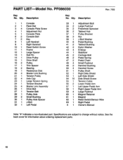
... Side Shield Screw Tension Cable Lower Pedal Arm Left Upper Pedal Arm Right Upper Pedal Arm Large Pushnut Magnet Retainer Magnet Reed Switch/Sensor Wire Right Pedal Owner's Manual Note: 'lir indicates a non-illustrated part. See the back cover for information about ordering replacement parts. 10 Qty. Description 1 1 Console 2 1 Pace Dial 3 4 Console Plate Screw 4 1 Adjustment Nut 5 1 Console Plate 6 2 Console Bolt 7 2 Key 8 1 Left Handrail 9 1 Right Handrail 10 1 Reed Switch Screw 11 1 Frame 12 1 Large Spacer 13 1 Roll Pin 14 1 Drive Pulley 15 1 Drive Shaft 16 2 Pulley 17 1 Thin...
... Side Shield Screw Tension Cable Lower Pedal Arm Left Upper Pedal Arm Right Upper Pedal Arm Large Pushnut Magnet Retainer Magnet Reed Switch/Sensor Wire Right Pedal Owner's Manual Note: 'lir indicates a non-illustrated part. See the back cover for information about ordering replacement parts. 10 Qty. Description 1 1 Console 2 1 Pace Dial 3 4 Console Plate Screw 4 1 Adjustment Nut 5 1 Console Plate 6 2 Console Bolt 7 2 Key 8 1 Left Handrail 9 1 Right Handrail 10 1 Reed Switch Screw 11 1 Frame 12 1 Large Spacer 13 1 Roll Pin 14 1 Drive Pulley 15 1 Drive Shaft 16 2 Pulley 17 1 Thin...
Owners Manual
Page 11
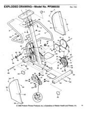
... 57 56 40 44 15 26 28 29 12 21 38 39 43 45 54 54 22 53 25 25 43 20 54 © 1993 Proform Fitness Products, Inc, a Subsidiary of Weider Health and Fitness, Inc. 11 EXPLODED DRAWING Model No.
... 57 56 40 44 15 26 28 29 12 21 38 39 43 45 54 54 22 53 25 25 43 20 54 © 1993 Proform Fitness Products, Inc, a Subsidiary of Weider Health and Fitness, Inc. 11 EXPLODED DRAWING Model No.
Owners Manual
Page 12
... of purchase. The MODEL NUMBER of this warranty is limited to the original purchaser. ORDERING REPLACEMENT PARTS To order replacement parts, simply call our Customer Service Department toll-free at one of purchase. until 6 p.m. Mountain Time (excluding holidays). To help us assist you specific legal rights. The KEY NUMBER and DESCRIPTION of the part(s) (see the front cover of the product (PROFORM® 860 stepper). 3. SOME STATES...
... of purchase. The MODEL NUMBER of this warranty is limited to the original purchaser. ORDERING REPLACEMENT PARTS To order replacement parts, simply call our Customer Service Department toll-free at one of purchase. until 6 p.m. Mountain Time (excluding holidays). To help us assist you specific legal rights. The KEY NUMBER and DESCRIPTION of the part(s) (see the front cover of the product (PROFORM® 860 stepper). 3. SOME STATES...


