
English Manual
Page 1
...! Read all safety precautions and instructions in this manual before using this manual for future reference. 0 O 0 PATENT PENDING OWNER'S MANUAL PF804030 Serial No. If you have questions, or find there are committed to you complete satisfaction through direct assistance from our factory. TM PRO•FORM® Model No. TO AVOID UNNECESSARY DELAYS, PLEASE CALL DIRECT TO OUR TOLL-FREE CUSTOMER HOT LINE.
...! Read all safety precautions and instructions in this manual before using this manual for future reference. 0 O 0 PATENT PENDING OWNER'S MANUAL PF804030 Serial No. If you have questions, or find there are committed to you complete satisfaction through direct assistance from our factory. TM PRO•FORM® Model No. TO AVOID UNNECESSARY DELAYS, PLEASE CALL DIRECT TO OUR TOLL-FREE CUSTOMER HOT LINE.
English Manual
Page 2
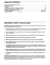
... become separated from the resistance cylinders, resulting in the accompanying literature before using. Use the cross training system only as you lift your feet on the pulleys as described. 2. If you use . This is normal for protection. Inspect and tighten all Instructions before using the cross training system. 1. Keep small children away from moving parts. Never release the arms, leg press plate or cam arm while weights are raised.
... become separated from the resistance cylinders, resulting in the accompanying literature before using. Use the cross training system only as you lift your feet on the pulleys as described. 2. If you use . This is normal for protection. Inspect and tighten all Instructions before using the cross training system. 1. Keep small children away from moving parts. Never release the arms, leg press plate or cam arm while weights are raised.
English Manual
Page 3
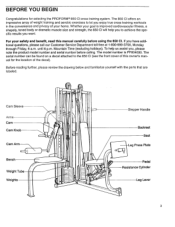
... Sleeve Arms Cam Cam Knob Cam Arm Bench Weight Tube Weights O O 0 O 0 0 Stepper Handle Backrest Seat Leg Press Plate Pedal Resistance Cylinder Leg Lever 3 The 850 CI offers an impressive array of weight training and aerobic exercises to the 850 CI (see the front cover of this manual carefully before calling. Whether your safety and benefit, read this owner's manual for selecting the PROFORM® 850 CI cross training system. Mountain Time (excluding holidays). Before reading further, please review the...
... Sleeve Arms Cam Cam Knob Cam Arm Bench Weight Tube Weights O O 0 O 0 0 Stepper Handle Backrest Seat Leg Press Plate Pedal Resistance Cylinder Leg Lever 3 The 850 CI offers an impressive array of weight training and aerobic exercises to the 850 CI (see the front cover of this manual carefully before calling. Whether your safety and benefit, read this owner's manual for selecting the PROFORM® 850 CI cross training system. Mountain Time (excluding holidays). Before reading further, please review the...
English Manual
Page 4
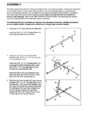
... 2. Refer to the PART IDENTIFICATION CHART accompanying this owner's manual for help identifying the small parts used . The following tools (not included) are also needed. 1. Press two 2" x 2" Caps (16) into the Base (81). 1 Insert four 5/16" x 2 1/2" Carriage Bolts (14) up through the Base (81) as shown in the drawings. ilar to distinguish the Leg Press Upright from the Arm Upright.) Attach the Leg Press Upright with two 5/16...
... 2. Refer to the PART IDENTIFICATION CHART accompanying this owner's manual for help identifying the small parts used . The following tools (not included) are also needed. 1. Press two 2" x 2" Caps (16) into the Base (81). 1 Insert four 5/16" x 2 1/2" Carriage Bolts (14) up through the Base (81) as shown in the drawings. ilar to distinguish the Leg Press Upright from the Arm Upright.) Attach the Leg Press Upright with two 5/16...
English Manual
Page 7
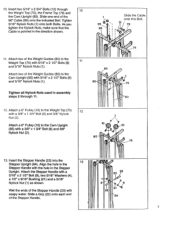
... 22 84 7 Tighten 5/16' Nylock Nuts (1) onto both Bolts. Attach a 6" Pulley (10) to the 11 Weight Top (75) with the hole in the direction shown. 11. 10. Insert two 5/16' x 2 3/4' Bolts (12) through 11. 1 99 kilt . 85 i Slide the Cable onto this Bolt. 1 79 !. Attach two of the Stepper Handle (23) with soapy water. Align the hole in assembly steps 2 through 10...
... 22 84 7 Tighten 5/16' Nylock Nuts (1) onto both Bolts. Attach a 6" Pulley (10) to the 11 Weight Top (75) with the hole in the direction shown. 11. 10. Insert two 5/16' x 2 3/4' Bolts (12) through 11. 1 99 kilt . 85 i Slide the Cable onto this Bolt. 1 79 !. Attach two of the Stepper Handle (23) with soapy water. Align the hole in assembly steps 2 through 10...

English Manual
Page 8
...Attach a Resistance Cylinder (91) to the Left Pedal (100) in the same manner. 14 J • 95 1O4 Ac),D94 101 104 ,zr- Make sure that the teeth on the correct side-the slotted bracket must be oriented as shown. Grease the lower axles on the hooks at the lower ends of the Spacer is turned... that the Pedal Is on the Retainer bend toward the Plastic Cap. Attach the Left Pedal (100) in the same manner. 17. Hook 0 100 Slot Make sure that the teeth on the Stepper Upright (84). 14. Attach a Pedal Cover (102) to the Right Pedal (101) with a 1/2" Screw (103). Press two Square ...
...Attach a Resistance Cylinder (91) to the Left Pedal (100) in the same manner. 14 J • 95 1O4 Ac),D94 101 104 ,zr- Make sure that the teeth on the correct side-the slotted bracket must be oriented as shown. Grease the lower axles on the hooks at the lower ends of the Spacer is turned... that the Pedal Is on the Retainer bend toward the Plastic Cap. Attach the Left Pedal (100) in the same manner. 17. Hook 0 100 Slot Make sure that the teeth on the Stepper Upright (84). 14. Attach a Pedal Cover (102) to the Right Pedal (101) with a 1/2" Screw (103). Press two Square ...

English Manual
Page 9
...Cable (96) to the Large Seat Frame [not shown], but the Small Seat Frame has square tubing.) Attach the Small Seat Frame (52) and one end of the two Arm Pads (72) with two 5/16' x 2 3/4" Bolts (12), 5/16' Washers (4) and 5/16" Nylock Nuts (1). Tap two 3/4' Retainers (63) and a 3/4" Plastic Cap (66) onto the Post. Press...the other end of the Handle is similar to the Arm Upright (86) with soapy water. As you tighten the upper Nylock Nut, make sure that the teeth on the Right Arm 19 (71). Apply grease to the Left Arm (70) in the direction shown. 12 20 71 c 31 32 70 22 k...
...Cable (96) to the Large Seat Frame [not shown], but the Small Seat Frame has square tubing.) Attach the Small Seat Frame (52) and one end of the two Arm Pads (72) with two 5/16' x 2 3/4" Bolts (12), 5/16' Washers (4) and 5/16" Nylock Nuts (1). Tap two 3/4' Retainers (63) and a 3/4" Plastic Cap (66) onto the Post. Press...the other end of the Handle is similar to the Arm Upright (86) with soapy water. As you tighten the upper Nylock Nut, make sure that the teeth on the Right Arm 19 (71). Apply grease to the Left Arm (70) in the direction shown. 12 20 71 c 31 32 70 22 k...

English Manual
Page 10
... Large Seat [not shown], but the Large Seat is against the Right Arm. Attach a 6" Plate (27) to the 6" Plate (27) with two 1/4" x 3/4" Screws (8). Do not overtighten the Nylock Nut. Lay the right 32" Cable (73) over a 3" Pulley (7). Tighten all three Screws attaching the Small Seat. 23. Make sure that the Cable remains between the Cable Trap and the Pulley. Tighten a 3/8" Nylock Nut (2) onto the Bolt. Attach one...
... Large Seat [not shown], but the Large Seat is against the Right Arm. Attach a 6" Plate (27) to the 6" Plate (27) with two 1/4" x 3/4" Screws (8). Do not overtighten the Nylock Nut. Lay the right 32" Cable (73) over a 3" Pulley (7). Tighten all three Screws attaching the Small Seat. 23. Make sure that the Cable remains between the Cable Trap and the Pulley. Tighten a 3/8" Nylock Nut (2) onto the Bolt. Attach one...

English Manual
Page 11
.... Do not fully tighten the Nylock Nut until assembly step 29 is between the Cable Trap (24) and the Pulley. Route the 137" Cable (97) around the 3' 24 Pulley (7) on the Leg Press Frame (88). Slide one end of the two 32' Cables (73) to each side of the Leg 29 Press Upright (87) with the 5/16' x 2' Bolt (61) and a 5/16' Nylock Nut (1). Attach a 3' Pulley (7) to the...
.... Do not fully tighten the Nylock Nut until assembly step 29 is between the Cable Trap (24) and the Pulley. Route the 137" Cable (97) around the 3' 24 Pulley (7) on the Leg Press Frame (88). Slide one end of the two 32' Cables (73) to each side of the Leg 29 Press Upright (87) with the 5/16' x 2' Bolt (61) and a 5/16' Nylock Nut (1). Attach a 3' Pulley (7) to the...
English Manual
Page 12
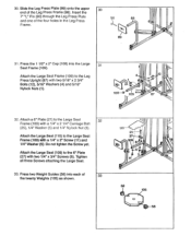
... each of 33 the twenty Weights (105) as shown. Attach the Large Seat (109) to the Leg Press Upright (87) with two 5/16" x 2 3/4" Bolts (12), 5/16" Washers (4) and 5/16" Nylock Nuts (1). Insert the 7" "L" Pin (90) through the Leg Press Plate and one of the Leg Press Frame (88). Press two Weight Guides (58) into the Large 31 Seat Frame (109). Attach the Large Seat Frame (109) to the...
... each of 33 the twenty Weights (105) as shown. Attach the Large Seat (109) to the Leg Press Upright (87) with two 5/16" x 2 3/4" Bolts (12), 5/16" Washers (4) and 5/16" Nylock Nuts (1). Insert the 7" "L" Pin (90) through the Leg Press Plate and one of the Leg Press Frame (88). Press two Weight Guides (58) into the Large 31 Seat Frame (109). Attach the Large Seat Frame (109) to the...
English Manual
Page 13
Attach a 3' Pulley (7) to the upper end of Weights. Press a Weight Tube Cap (77) into the Top Weight (105) on each stack of the Weight Tube with a 3/8" x 1 3/4' Bolt (6) and 3/8" Nylock Nut (2). Pin Grooves 57 105 1O5 35. Find the upper end of the Weights are turned so the pin grooves are downward, and are on the Weight Top (75). Attach the 98° Cable (99) to each...
Attach a 3' Pulley (7) to the upper end of Weights. Press a Weight Tube Cap (77) into the Top Weight (105) on each stack of the Weight Tube with a 3/8" x 1 3/4' Bolt (6) and 3/8" Nylock Nut (2). Pin Grooves 57 105 1O5 35. Find the upper end of the Weights are turned so the pin grooves are downward, and are on the Weight Top (75). Attach the 98° Cable (99) to each...
English Manual
Page 14
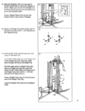
... 5/16" Nylock Nut (1). Lay the 195' Cable (98) over a 3" Pulley (7). Tighten a 3/8" Nylock Nut (2) onto the Bolt. Lay the 195" Cable (98) over the Wide 3' VPulley (40). Insert the 195" Cable (98) through the Cam Upright (85). Slide the Wide Cable Trap (20) and the Pulley onto the 3/8" x 4" Bolt (113). Attach the Pulley to the Cam Upright (85) with a 3/8" x 1 3/4" Bolt (6) and 3/8' Nylock Nut (2). 38 79...
... 5/16" Nylock Nut (1). Lay the 195' Cable (98) over a 3" Pulley (7). Tighten a 3/8" Nylock Nut (2) onto the Bolt. Lay the 195" Cable (98) over the Wide 3' VPulley (40). Insert the 195" Cable (98) through the Cam Upright (85). Slide the Wide Cable Trap (20) and the Pulley onto the 3/8" x 4" Bolt (113). Attach the Pulley to the Cam Upright (85) with a 3/8" x 1 3/4" Bolt (6) and 3/8' Nylock Nut (2). 38 79...

English Manual
Page 15
... Nut (2). Find the upper end of the Cable should pro- Attach the 195' Cable (98) to the upper end of the Cable. Attach the Pulley to the Leg Press Upright (87) with a 5/16' x 1 1/2' 1 Bolt (54) and 5/16' Nylock Nut (1). / 77 Press a Weight Tube Cap (77) into the lower 78 end of the Weight Tube (78). 105 1 Insert the Weight Tube (78) into the indicated Long 'U" Bracket...
... Nut (2). Find the upper end of the Cable should pro- Attach the 195' Cable (98) to the upper end of the Cable. Attach the Pulley to the Leg Press Upright (87) with a 5/16' x 1 1/2' 1 Bolt (54) and 5/16' Nylock Nut (1). / 77 Press a Weight Tube Cap (77) into the lower 78 end of the Weight Tube (78). 105 1 Insert the Weight Tube (78) into the indicated Long 'U" Bracket...

English Manual
Page 16
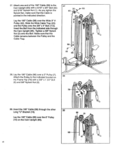
... of 1 the Cable. 43. Hold the Cam Sleeve (44) against the Cam Upright (85) as shown. Hold a Cam Sleeve Bushing (35) inside the Cam Sleeve (44). Route the 137' Cable (97) under the indicat- 43 ed 3" Pulley (7) on the lower end. Slide a 3" Pulley (7) onto the 3/8" x 5" Bolt (36). Tighten a 3/8" Nylock Nut (2) onto the Bolt. Insert the threaded end of the Cable should pro-
... of 1 the Cable. 43. Hold the Cam Sleeve (44) against the Cam Upright (85) as shown. Hold a Cam Sleeve Bushing (35) inside the Cam Sleeve (44). Route the 137' Cable (97) under the indicat- 43 ed 3" Pulley (7) on the lower end. Slide a 3" Pulley (7) onto the 3/8" x 5" Bolt (36). Tighten a 3/8" Nylock Nut (2) onto the Bolt. Insert the threaded end of the Cable should pro-
English Manual
Page 19
... the cables does not move smoothly, locate and correct the problem before using the cross training system, test the cables and pulleys. Make sure that the cable moves smoothly over the pulleys. I CI I 'RADIUS CAM ARM' Cam Decals 0 v moomt6® Cam Decals I "INDEPENDENT ACTION STEPPER' (Place at this owner's manual. 56. "SPEED LINK' Note: The words WNW 'FAST' must be damaged when used with heavy weight. 19 Move the arms, leg press plate...
... the cables does not move smoothly, locate and correct the problem before using the cross training system, test the cables and pulleys. Make sure that the cable moves smoothly over the pulleys. I CI I 'RADIUS CAM ARM' Cam Decals 0 v moomt6® Cam Decals I "INDEPENDENT ACTION STEPPER' (Place at this owner's manual. 56. "SPEED LINK' Note: The words WNW 'FAST' must be damaged when used with heavy weight. 19 Move the arms, leg press plate...
English Manual
Page 20
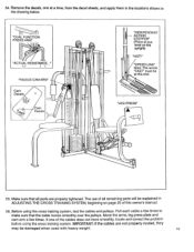
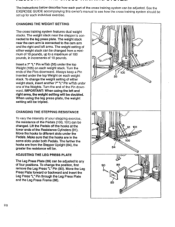
... Weights. To change the position, first remove the Leg Press "L" Pin (90). ADJUSTING THE LEG PRESS PLATE The Leg Press Plate (89) can be changed from the Stepper Upright (84), the greater the resistance will be tripled. The instructions below describe how each part of the cross training system can be changed . Always keep a Pin inserted under one of the Pins downward. When using the left arms. The weight setting of either weight stack, insert another 7" "L" Pin...
... Weights. To change the position, first remove the Leg Press "L" Pin (90). ADJUSTING THE LEG PRESS PLATE The Leg Press Plate (89) can be changed from the Stepper Upright (84), the greater the resistance will be tripled. The instructions below describe how each part of the cross training system can be changed . Always keep a Pin inserted under one of the Pins downward. When using the left arms. The weight setting of either weight stack, insert another 7" "L" Pin...
English Manual
Page 21
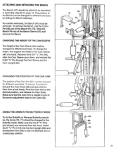
... the Cam Arm (50) must be removed. The position of the seven adjustment holes in assembly step 52 on page 18. To change the height, first support the weight of the Cam Sleeve with one of the Bench can be changed for different exercises. USING THE ARMS IN THE BUTTERFLY MODE To do the Butterfly or Reverse Butterfly exercises, the Arms (70, 71) should be attached as...
... the Cam Arm (50) must be removed. The position of the seven adjustment holes in assembly step 52 on page 18. To change the height, first support the weight of the Cam Sleeve with one of the Bench can be changed for different exercises. USING THE ARMS IN THE BUTTERFLY MODE To do the Butterfly or Reverse Butterfly exercises, the Arms (70, 71) should be attached as...

English Manual
Page 22
Make sure the 5" "L" Pin (not shown) is removed from the Moment Arm (69). Insert the two Arm "L" Pins (62) into the Moment Arm (69) and the Arms to the press mode. USING THE ARMS IN THE PRESS MODE To do the Bench Press or Military Press exercises, the Arms (70, 71) should be changed to lock the Arms in a stationary position. 62 69 70 71 22
Make sure the 5" "L" Pin (not shown) is removed from the Moment Arm (69). Insert the two Arm "L" Pins (62) into the Moment Arm (69) and the Arms to the press mode. USING THE ARMS IN THE PRESS MODE To do the Bench Press or Military Press exercises, the Arms (70, 71) should be changed to lock the Arms in a stationary position. 62 69 70 71 22
English Manual
Page 23
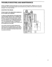
... information about ordering replacement parts. If the cables cannot be properly tightened by tightening the 5/16" Nylock Nuts (1), the cables may need to the'weight stack near the cam arm, find the Long `U" Bracket (19) labeled IA" in the cables before resistance is slack in the drawing at the right. To adjust the cable attached to be replaced. TROUBLE-SHOOTING AND MAINTENANCE Inspect and tighten all parts each time you use...
... information about ordering replacement parts. If the cables cannot be properly tightened by tightening the 5/16" Nylock Nuts (1), the cables may need to the'weight stack near the cam arm, find the Long `U" Bracket (19) labeled IA" in the cables before resistance is slack in the drawing at the right. To adjust the cable attached to be replaced. TROUBLE-SHOOTING AND MAINTENANCE Inspect and tighten all parts each time you use...
English Manual
Page 24
... SET FORTH HEREIN. The MODEL NUMBER of the product (PROFORM® 850 CI cross training system).. 3. The KEY NUMBER and DESCRIPTION of the part(s) from the date of its authorized service centers. All returns must be pre-authorized by PROFORM. This warranty gives you , please be free from defects in USA The NAME of the product (PF804030). 2. LIMITED WARRANTY Proform Fitness Products, Inc. ("PROFORM"), warrants this owner's manual. No other rights which warranty...
... SET FORTH HEREIN. The MODEL NUMBER of the product (PROFORM® 850 CI cross training system).. 3. The KEY NUMBER and DESCRIPTION of the part(s) from the date of its authorized service centers. All returns must be pre-authorized by PROFORM. This warranty gives you , please be free from defects in USA The NAME of the product (PF804030). 2. LIMITED WARRANTY Proform Fitness Products, Inc. ("PROFORM"), warrants this owner's manual. No other rights which warranty...

