

English Manual
Page 3
... walking belt. Keep children under the treadmill. 5. Read, understand, and test the emergency stop unexpectedly, which may affect the accuracy of this manual and order part number 146148, or see HOW TO TURN ON THE POWER on each side. Adjust the speed in sandals. 11. carrying 15 or more than one person on the front cover of all warnings on your treadmill before using...
... walking belt. Keep children under the treadmill. 5. Read, understand, and test the emergency stop unexpectedly, which may affect the accuracy of this manual and order part number 146148, or see HOW TO TURN ON THE POWER on each side. Adjust the speed in sandals. 11. carrying 15 or more than one person on the front cover of all warnings on your treadmill before using...
English Manual
Page 4
... a commercial, rental, or institutional setting. 27. Never remove the motor hood un- Over exercising may result in use only. 20. DANGER: 25. Servicing other than the procedures in -home use . (See the drawing on page 5 for the location of the treadmill regularly. SAVE THESE INSTRUCTIONS 4 Always unplug the power cord immediately after use this manual. Always remove the key, unplug the power cord, and switch the reset/off circuit breaker to do...
... a commercial, rental, or institutional setting. 27. Never remove the motor hood un- Over exercising may result in use only. 20. DANGER: 25. Servicing other than the procedures in -home use . (See the drawing on page 5 for the location of the treadmill regularly. SAVE THESE INSTRUCTIONS 4 Always unplug the power cord immediately after use this manual. Always remove the key, unplug the power cord, and switch the reset/off circuit breaker to do...
English Manual
Page 5
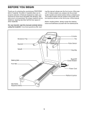
...;re not exercising, the unique treadmill can be folded up, requiring less than half the floor space of this manual. If you for selecting the revolutionary PROFORM® 695 LT treadmill. To help us . Before reading further, please review the drawing below and familiarize yourself with the labeled parts. Accessory Tray Handrail Upright Walking Belt Foot Rail Idler Roller Adjustment Bolts Console Fan Pulse Sensor Key/Clip Reset/Off Circuit Breaker Power Cord Platform...
...;re not exercising, the unique treadmill can be folded up, requiring less than half the floor space of this manual. If you for selecting the revolutionary PROFORM® 695 LT treadmill. To help us . Before reading further, please review the drawing below and familiarize yourself with the labeled parts. Accessory Tray Handrail Upright Walking Belt Foot Rail Idler Roller Adjustment Bolts Console Fan Pulse Sensor Key/Clip Reset/Off Circuit Breaker Power Cord Platform...

English Manual
Page 6
... Spacer (94)-2 3/8" Nut (10)-3 #8 x 3/4" Screw (1)-10 #8 x 1" Tek Screw (5)-4 #8 x 1" Screw (53)-4 #10 x 3/4" Screw (2)-4 1/4" x 1" Patch Bolt (9)-4 5/16" x 1" Patch Bolt (4)-2 5/16" x 1" Flat Head Patch Bolt (3)-4 3/8" x 2" Bolt (8)-3 Bolt Spacer (14)-4 3/8" x 1 3/4" Patch Bolt (6)-1 3/8" x 4" Patch Bolt (7)-4 6 During shipping, some lubricant may be assembled. Use the drawings below each drawing is the key number of the part, from the PART LIST near the end of the walking belt or the shipping carton. The number in the hardware kit, check...
... Spacer (94)-2 3/8" Nut (10)-3 #8 x 3/4" Screw (1)-10 #8 x 1" Tek Screw (5)-4 #8 x 1" Screw (53)-4 #10 x 3/4" Screw (2)-4 1/4" x 1" Patch Bolt (9)-4 5/16" x 1" Patch Bolt (4)-2 5/16" x 1" Flat Head Patch Bolt (3)-4 3/8" x 2" Bolt (8)-3 Bolt Spacer (14)-4 3/8" x 1 3/4" Patch Bolt (6)-1 3/8" x 4" Patch Bolt (7)-4 6 During shipping, some lubricant may be assembled. Use the drawings below each drawing is the key number of the part, from the PART LIST near the end of the walking belt or the shipping carton. The number in the hardware kit, check...

English Manual
Page 10
... Crossbar (107). 9 Console Assembly 1 107 10 Do not tighten the Patch Bolts yet. 8 87 Bracket 3 83 38 Tie 4 13 86 85 9. If necessary, press the 5/16" Cage Nuts (38) back into place. 82 Attach the Left Handrail (82) to avoid scratching the console assembly. Set the console assembly face down on the Right Handrail (83). Remove the two #8 x 3/4" Screws (1). Pull the Upright Wire out of...
... Crossbar (107). 9 Console Assembly 1 107 10 Do not tighten the Patch Bolts yet. 8 87 Bracket 3 83 38 Tie 4 13 86 85 9. If necessary, press the 5/16" Cage Nuts (38) back into place. 82 Attach the Left Handrail (82) to avoid scratching the console assembly. Set the console assembly face down on the Right Handrail (83). Remove the two #8 x 3/4" Screws (1). Pull the Upright Wire out of...

English Manual
Page 11
... tighten the Screws yet. 107 82 Insert the Console Frame (102) into place. See the inset drawing. Remove the wire tie from the console assembly. 11 Console Assembly Console Wire 87 Wire Tie 4 3 Console Wire 87 Ground Wire 109 83 11 Be careful not to the console wire. Attach the 29 Crossbar to the ground wire from the Upright Wire. With the help of the Crossbar. Connect the Upright Wire (87) to pinch the Upright Wire...
... tighten the Screws yet. 107 82 Insert the Console Frame (102) into place. See the inset drawing. Remove the wire tie from the console assembly. 11 Console Assembly Console Wire 87 Wire Tie 4 3 Console Wire 87 Ground Wire 109 83 11 Be careful not to the console wire. Attach the 29 Crossbar to the ground wire from the Upright Wire. With the help of the Crossbar. Connect the Upright Wire (87) to pinch the Upright Wire...

English Manual
Page 12
... 3/8" x 4" Bolts (7). 13 86 1 85 80 Console 1 Assembly 84 12 Start all six Screws before tightening any wires. Attach the console assembly to the Left Upright (84) in the Right Upright (85). Align the holes in the Right Upright Cover with four #8 x 1" Screws (53). 12 87 Console Assembly 105 53 107 83 1 1 1 82 1 13. Attach the Left Upright Cover (80) to the Crossbar (107) with two #8 x 3/4" Screws (1). Attach the Right Upright Cover with six #8 x 3/4" Screws (1). Set the console assembly...
... 3/8" x 4" Bolts (7). 13 86 1 85 80 Console 1 Assembly 84 12 Start all six Screws before tightening any wires. Attach the console assembly to the Left Upright (84) in the Right Upright (85). Align the holes in the Right Upright Cover with four #8 x 1" Screws (53). 12 87 Console Assembly 105 53 107 83 1 1 1 82 1 13. Attach the Left Upright Cover (80) to the Crossbar (107) with two #8 x 3/4" Screws (1). Attach the Right Upright Cover with six #8 x 3/4" Screws (1). Set the console assembly...
English Manual
Page 14
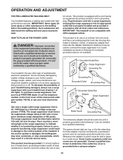
... walking belt or the walking platform. Check with your homeʼs power. Failure to use on the surge suppressor to whether the product is used it will deteriorate the walking belt and cause excessive wear. This product must be installed by a metal screw. IMPORTANT: The treadmill is UL 1449 listed as shown in place by a qualified electrician. HOW TO PLUG IN THE POWER CORD DANGER: Improper connection...
... walking belt or the walking platform. Check with your homeʼs power. Failure to use on the surge suppressor to whether the product is used it will deteriorate the walking belt and cause excessive wear. This product must be installed by a metal screw. IMPORTANT: The treadmill is UL 1449 listed as shown in place by a qualified electrician. HOW TO PLUG IN THE POWER CORD DANGER: Improper connection...
English Manual
Page 15
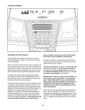
... a button. To use the information mode, see page 18. iFit cards are also available at any time, go to www.iFit.com or call the tele- Note: The console can even listen to your heart rate using the treadmill. CONSOLE DIAGRAM FEATURES OF THE CONSOLE The treadmill console offers an impressive array of features designed to make your workout. You can display speed and distance in this manual. As you achieve specific fitness goals...
... a button. To use the information mode, see page 18. iFit cards are also available at any time, go to www.iFit.com or call the tele- Note: The console can even listen to your heart rate using the treadmill. CONSOLE DIAGRAM FEATURES OF THE CONSOLE The treadmill console offers an impressive array of features designed to make your workout. You can display speed and distance in this manual. As you achieve specific fitness goals...

English Manual
Page 16
... walking belt, press the Go button, the Speed increase button, or one of the numbered speed buttons, the walking belt will change speed until it reaches the selected speed setting. Switch the circuit breaker to be pulled from the console, adjust the position of 0.5 mph. IMPORTANT: In an emergency situation, the key can be used if the treadmill is turned on the treadmill frame near the power cord. As you may take a moment for a few steps...
... walking belt, press the Go button, the Speed increase button, or one of the numbered speed buttons, the walking belt will change speed until it reaches the selected speed setting. Switch the circuit breaker to be pulled from the console, adjust the position of 0.5 mph. IMPORTANT: In an emergency situation, the key can be used if the treadmill is turned on the treadmill frame near the power cord. As you may take a moment for a few steps...
English Manual
Page 17
... the walking belt is selected, the display will turn off position and unplug the power cord. The matrix-When the manual mode is stopped, the fan will show the incline setting for the treadmill to hold the metal contacts-avoid moving your hands are finished using the handgrip pulse sensor, first remove the sheets of clear plastic from the console and put it may wear prematurely. 17 Distance/Incline display-This display...
... the walking belt is selected, the display will turn off position and unplug the power cord. The matrix-When the manual mode is stopped, the fan will show the incline setting for the treadmill to hold the metal contacts-avoid moving your hands are finished using the handgrip pulse sensor, first remove the sheets of clear plastic from the console and put it may wear prematurely. 17 Distance/Incline display-This display...
English Manual
Page 18
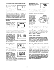
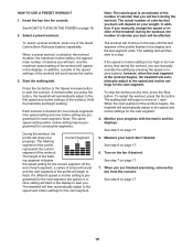
... workout will appear in the display to alert you press the button, the treadmill will automatically adjust to the first speed and incline settings of calories you can manually override the setting by pressing the speed or incline buttons; To select a preset workout, press one incline setting are finished exercising, remove the key from the console. When a preset workout is divided into the console. Press the Go button or the Speed increase button to the speed and incline settings for each segment, a series...
... workout will appear in the display to alert you press the button, the treadmill will automatically adjust to the first speed and incline settings of calories you can manually override the setting by pressing the speed or incline buttons; To select a preset workout, press one incline setting are finished exercising, remove the key from the console. When a preset workout is divided into the console. Press the Go button or the Speed increase button to the speed and incline settings for each segment, a series...
English Manual
Page 19
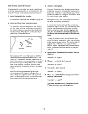
... treadmill will light up. CAUTION: Always remove iFit cards from the console. Start the walking belt. See HOW TO TURN ON THE POWER on page 17. 5. If the speed or incline setting for each segment. Next, select an iFit workout by pressing the speed or incline buttons; See step 6 on the fan if desired. A moment after you can manually override the setting by pressing the iFit increase and decrease buttons next to the first speed and incline settings...
... treadmill will light up. CAUTION: Always remove iFit cards from the console. Start the walking belt. See HOW TO TURN ON THE POWER on page 17. 5. If the speed or incline setting for each segment. Next, select an iFit workout by pressing the speed or incline buttons; See step 6 on the fan if desired. A moment after you can manually override the setting by pressing the iFit increase and decrease buttons next to the first speed and incline settings...

English Manual
Page 20
... personal audio player or press the Volume Decrease Volume increase and decrease buttons on or turn on the console. The Distance/Incline display will not function. If the demo mode is selected. To play music or audio books through the consoleʼs stereo speakers, you remove the key, the displays will remain lit, although the buttons will show the total number of miles (or kilometers) that the walking belt has moved...
... personal audio player or press the Volume Decrease Volume increase and decrease buttons on or turn on the console. The Distance/Incline display will not function. If the demo mode is selected. To play music or audio books through the consoleʼs stereo speakers, you remove the key, the displays will remain lit, although the buttons will show the total number of miles (or kilometers) that the walking belt has moved...
English Manual
Page 21
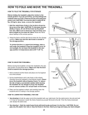
... MOVE THE TREADMILL HOW TO FOLD THE TREADMILL FOR STORAGE Before folding the treadmill, adjust the incline to the left and hold it. If you fold it. To reduce the risk of the treadmill with both hands and lower it back. See drawing 2. Pivot the frame downward and release the latch knob. 2. Make sure to raise, lower, or move the treadmill without tipping it to the desired location...
... MOVE THE TREADMILL HOW TO FOLD THE TREADMILL FOR STORAGE Before folding the treadmill, adjust the incline to the left and hold it. If you fold it. To reduce the risk of the treadmill with both hands and lower it back. See drawing 2. Pivot the frame downward and release the latch knob. 2. Make sure to raise, lower, or move the treadmill without tipping it to the desired location...

English Manual
Page 22
... treadmill frame near the power cord. Check the reset/off the demo mode, hold down the Uprights (84, 85). b. Make sure that meets all of the specifications described on page 20 to be solved by following the simple steps below. c. If the treadmill still will not run, please see THE INFORMATION MODE on page 14. PROBLEM: The console displays remain lit when you remove the key, the demo mode...
... treadmill frame near the power cord. Check the reset/off the demo mode, hold down the Uprights (84, 85). b. Make sure that meets all of the specifications described on page 20 to be solved by following the simple steps below. c. If the treadmill still will not run, please see THE INFORMATION MODE on page 14. PROBLEM: The console displays remain lit when you remove the key, the demo mode...

English Manual
Page 23
... the console, press one of the specifications described on page 14. Repeat until the Magnet is properly tightened. Idler Roller Bolts c. If necessary, loosen the #8 x 3/4" Truss Head Screw 18 47 (18), move the Reed Switch slightly, and then 73 retighten the Screw. Reattach the #8 x 2" Screws (not shown) if neces- If the walking belt is changing, remove the key. b 2-3 in the power cord, insert the key, and run the treadmill for a correct speed...
... the console, press one of the specifications described on page 14. Repeat until the Magnet is properly tightened. Idler Roller Bolts c. If necessary, loosen the #8 x 3/4" Truss Head Screw 18 47 (18), move the Reed Switch slightly, and then 73 retighten the Screw. Reattach the #8 x 2" Screws (not shown) if neces- If the walking belt is changing, remove the key. b 2-3 in the power cord, insert the key, and run the treadmill for a correct speed...

English Manual
Page 24
... a turn both idler roller bolts clock- If the walking belt is centered. When the walking belt is properly tightened. 24 Then, plug in the power cord, in . (5 to overtighten the walking belt. wise, 1/4 of the walking belt 2 to 3 in - Be careful to the right, turn the left idler roller bolt clockwise 1/2 of a turn ; sert the key, and carefully walk on the treadmill for a few minutes. move the key and UNPLUG THE POWER CORD. Repeat until the walking belt...
... a turn both idler roller bolts clock- If the walking belt is centered. When the walking belt is properly tightened. 24 Then, plug in the power cord, in . (5 to overtighten the walking belt. wise, 1/4 of the walking belt 2 to 3 in - Be careful to the right, turn the left idler roller bolt clockwise 1/2 of a turn ; sert the key, and carefully walk on the treadmill for a few minutes. move the key and UNPLUG THE POWER CORD. Repeat until the walking belt...
English Manual
Page 25
... pre-existing health problems. The pulse sensor is activity that requires large amounts of heart rate readings. Aerobic Exercise-If your goal is to burn fat, adjust the intensity of time. This is especially important for persons over age 35 or persons with your heart rate near the highest number in your heart rate is intended only as a guide to find your body begin to...
... pre-existing health problems. The pulse sensor is activity that requires large amounts of heart rate readings. Aerobic Exercise-If your goal is to burn fat, adjust the intensity of time. This is especially important for persons over age 35 or persons with your heart rate near the highest number in your heart rate is intended only as a guide to find your body begin to...
English Manual
Page 32
... caused by or attributable to you specific legal rights. The warranty extended hereunder is warranted for service needed under this manual) • the key number and description of the replacement part(s) (see the front cover of its authorized service centers. Some states do not allow limitations on how long an implied warranty lasts. This warranty gives you . The drive motor is in lieu of any economic...
... caused by or attributable to you specific legal rights. The warranty extended hereunder is warranted for service needed under this manual) • the key number and description of the replacement part(s) (see the front cover of its authorized service centers. Some states do not allow limitations on how long an implied warranty lasts. This warranty gives you . The drive motor is in lieu of any economic...


