

Men Manual
Page 2
... in the location shown. If a decal is a registered trademark of the warning decals. TABLE OF CONTENTS WARNING DECAL PLACEMENT 2 IMPORTANT PRECAUTIONS 3 BEFORE YOU BEGIN 5 ASSEMBLY 6 OPERATION AND ADJUSTMENT 13 HOW TO FOLD AND MOVE THE TREADMILL 19 TROUBLESHOOTING 21 EXERCISE GUIDELINES 24 PART LIST 26 EXPLODED DRAWING 28 ORDERING REPLACEMENT PARTS Back Cover WARNING DECAL PLACEMENT This drawing shows the locations of ICON IP, Inc...
... in the location shown. If a decal is a registered trademark of the warning decals. TABLE OF CONTENTS WARNING DECAL PLACEMENT 2 IMPORTANT PRECAUTIONS 3 BEFORE YOU BEGIN 5 ASSEMBLY 6 OPERATION AND ADJUSTMENT 13 HOW TO FOLD AND MOVE THE TREADMILL 19 TROUBLESHOOTING 21 EXERCISE GUIDELINES 24 PART LIST 26 EXPLODED DRAWING 28 ORDERING REPLACEMENT PARTS Back Cover WARNING DECAL PLACEMENT This drawing shows the locations of ICON IP, Inc...

Men Manual
Page 3
... the telephone number on the warranty card accompanying this treadmill are standing on any exercise program, consult your local electronics store. 12. Never move the walking belt while the power is not a medical device. Never allow more amps. Never start the treadmill while you are adequately informed of the specifications described on each side. Always hold the handrails while using the treadmill. The pulse sensor is turned off. ICON assumes...
... the telephone number on the warranty card accompanying this treadmill are standing on any exercise program, consult your local electronics store. 12. Never move the walking belt while the power is not a medical device. Never allow more amps. Never start the treadmill while you are adequately informed of the specifications described on each side. Always hold the handrails while using the treadmill. The pulse sensor is turned off. ICON assumes...

Men Manual
Page 4
... in use , before cleaning the treadmill, and before performing the mainte- Always remove the key, unplug the power cord, and switch the reset/off circuit breaker to the off the rack, causing the user to do so by an authorized service representative only. 26. Inspect and properly tighten all parts of the circuit breaker.) 21. nance and adjustment procedures described in this manual. Use the...
... in use , before cleaning the treadmill, and before performing the mainte- Always remove the key, unplug the power cord, and switch the reset/off circuit breaker to the off the rack, causing the user to do so by an authorized service representative only. 26. Inspect and properly tighten all parts of the circuit breaker.) 21. nance and adjustment procedures described in this manual. Use the...

Men Manual
Page 5
... manual. Accessory Tray Handrail Storage Latch Dumbbells Upright Walking Belt Foot Rail Book Rack Console Pulse Sensor Key/Clip Dumbbell Rack Reset/Off Circuit Breaker Power Cord Idler Roller Adjustment Bolts Platform Cushion 5 If you for selecting the new PROFORM® 680 MRT treadmill. Before reading further, please review the drawing below and familiarize yourself with the labeled parts. For your workouts at home more effective. To help us . The model number and the location of the serial number...
... manual. Accessory Tray Handrail Storage Latch Dumbbells Upright Walking Belt Foot Rail Book Rack Console Pulse Sensor Key/Clip Dumbbell Rack Reset/Off Circuit Breaker Power Cord Idler Roller Adjustment Bolts Platform Cushion 5 If you for selecting the new PROFORM® 680 MRT treadmill. Before reading further, please review the drawing below and familiarize yourself with the labeled parts. For your workouts at home more effective. To help us . The model number and the location of the serial number...

Men Manual
Page 6
...)-2 M4.2 x 19mm Screw (1)-6 M4.2 x 25mm Tek Screw (2)-4 #8 x 1/2" Screw (22)-1 1/4" x 3/4" Bolt (98)-4 M8 x 25mm Bolt (6)-4 M10 x 50mm Bolt (27)-2 M10 x 96mm Bolt (5)-4 6 Note: If a part is not in the hardware kit, check to identify the assembly hardware. This is completed. To avoid damaging plastic parts, do not use power tools for assembly. Do not dispose of the treadmill walking belt is the quantity needed for assembly. The number after the...
...)-2 M4.2 x 19mm Screw (1)-6 M4.2 x 25mm Tek Screw (2)-4 #8 x 1/2" Screw (22)-1 1/4" x 3/4" Bolt (98)-4 M8 x 25mm Bolt (6)-4 M10 x 50mm Bolt (27)-2 M10 x 96mm Bolt (5)-4 6 Note: If a part is not in the hardware kit, check to identify the assembly hardware. This is completed. To avoid damaging plastic parts, do not use power tools for assembly. Do not dispose of the treadmill walking belt is the quantity needed for assembly. The number after the...

Men Manual
Page 11
... location shown. Attach the console ground wire to the console assembly with three M4.2 x 19mm Screws (1). 12 Start all three Screws before tightening any of them ; Set the console assembly on the Right Handrail (90) and the Left Handrail (not shown). Start all three Screws before tightening any of the top as shown. IF THE CONNECTORS ARE NOT CONNECTED PROPERLY, THE CONSOLE MAY BE DAMAGED WHEN THE POWER IS TURNED...
... location shown. Attach the console ground wire to the console assembly with three M4.2 x 19mm Screws (1). 12 Start all three Screws before tightening any of them ; Set the console assembly on the Right Handrail (90) and the Left Handrail (not shown). Start all three Screws before tightening any of the top as shown. IF THE CONNECTORS ARE NOT CONNECTED PROPERLY, THE CONSOLE MAY BE DAMAGED WHEN THE POWER IS TURNED...
Men Manual
Page 12
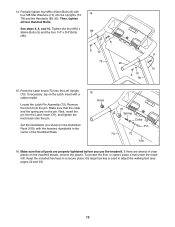
...) into the Uprights (73, 14 78) and the Handrails (89, 90). Remove the knob from the pin. See steps 5, 8, and 10. Press the Latch Insert (70) into the Latch Insert (70), and tighten the knob back onto the pin. Keep the included hex keys in the center of clear plastic on the pin. 14. the large hex key is used to adjust the walking belt (see pages 22...
...) into the Uprights (73, 14 78) and the Handrails (89, 90). Remove the knob from the pin. See steps 5, 8, and 10. Press the Latch Insert (70) into the Latch Insert (70), and tighten the knob back onto the pin. Keep the included hex keys in the center of clear plastic on the pin. 14. the large hex key is used to adjust the walking belt (see pages 22...

Men Manual
Page 13
... conditions or from the adapter must be a monitoring light on the warranty card accompanying this manual, or see drawing 1 at the right). HOW TO PLUG IN THE POWER CORD DANGER: Improper connection of the equipment-grounding conductor can be held in damage to the walking belt or the walking platform. Your treadmill, like extending from other appliances being damaged, always use a properly functioning surge...
... conditions or from the adapter must be a monitoring light on the warranty card accompanying this manual, or see drawing 1 at the right). HOW TO PLUG IN THE POWER CORD DANGER: Improper connection of the equipment-grounding conductor can be held in damage to the walking belt or the walking platform. Your treadmill, like extending from other appliances being damaged, always use a properly functioning surge...

Men Manual
Page 14
... you use the manual mode, you exercise, the console will display instant exercise feedback. You can change the unit of measurement, see page 23). In addition, the console offers six iFit custom-fit preset workouts. Each workout automatically controls the speed and incline of the treadmill as it guides you use the information mode, see page 15. To use the treadmill, observe the alignment of the walking belt, and center the walking belt if necessary (see THE INFORMATION MODE...
... you use the manual mode, you exercise, the console will display instant exercise feedback. You can change the unit of measurement, see page 23). In addition, the console offers six iFit custom-fit preset workouts. Each workout automatically controls the speed and incline of the treadmill as it guides you use the information mode, see page 15. To use the treadmill, observe the alignment of the walking belt, and center the walking belt if necessary (see THE INFORMATION MODE...

Men Manual
Page 15
... a moment for the walking belt to the reset position. If you press a button, it may damage the console displays or other electrical components. 1. Change the incline of the speed buttons numbered 2 through 10. Note: After you press one of the treadmill as you press a button, it may take a moment for a few steps backward; HOW TO TURN ON THE POWER HOW TO USE THE MANUAL MODE IMPORTANT: If the treadmill has been exposed to...
... a moment for the walking belt to the reset position. If you press a button, it may damage the console displays or other electrical components. 1. Change the incline of the speed buttons numbered 2 through 10. Note: After you press one of the treadmill as you press a button, it may take a moment for a few steps backward; HOW TO TURN ON THE POWER HOW TO USE THE MANUAL MODE IMPORTANT: If the treadmill has been exposed to...

Men Manual
Page 16
... rails, press the Stop button, and adjust the incline of the walking belt. 5. Press the Display button repeatedly until the upper display shows the information that your heart rate will also show the approximate number of the elapsed time. Follow your hands. As you exercise, the lower left display can show the elapsed time and the distance that you may wear prematurely. 16 The lower left display- Before using the treadmill, switch the reset/off...
... rails, press the Stop button, and adjust the incline of the walking belt. 5. Press the Display button repeatedly until the upper display shows the information that your heart rate will also show the approximate number of the elapsed time. Follow your hands. As you exercise, the lower left display can show the elapsed time and the distance that you may wear prematurely. 16 The lower left display- Before using the treadmill, switch the reset/off...

Men Manual
Page 17
... the workout begins, the treadmill will automatically adjust to move at any time, press the Stop button. ment. The walking belt will sound at any time during the workout, you are programmed for the next segment. 5. See step 5 on page 15. 2. You can manually override the setting by pressing the speed or incline buttons; Measure your progress with the displays. See step 6 on page 16. 17 Note: The name, number, and...
... the workout begins, the treadmill will automatically adjust to move at any time, press the Stop button. ment. The walking belt will sound at any time during the workout, you are programmed for the next segment. 5. See step 5 on page 15. 2. You can manually override the setting by pressing the speed or incline buttons; Measure your progress with the displays. See step 6 on page 16. 17 Note: The name, number, and...

Men Manual
Page 18
... the buttons will appear in the power cord, switch the reset/off circuit breaker to change the unit of measurement if desired. To exit the information mode, remove the key from the console. 18 To exercise your head. To turn on , a "d" will not function. Exercises using dumbbells should be used . THE INFORMATION MODE HOW TO USE THE DUMBBELLS The console features an information mode that keeps track of the total distance that the walking belt has moved...
... the buttons will appear in the power cord, switch the reset/off circuit breaker to change the unit of measurement if desired. To exit the information mode, remove the key from the console. 18 To exercise your head. To turn on , a "d" will not function. Exercises using dumbbells should be used . THE INFORMATION MODE HOW TO USE THE DUMBBELLS The console features an information mode that keeps track of the total distance that the walking belt has moved...
Men Manual
Page 19
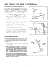
... STORAGE Before folding the treadmill, adjust the incline to bend your legs and keep your back straight as described above 85° F (30° C). Make sure that the latch pin is aligned with the heaviest dumbbell in the location shown by the plastic foot rails. Place one of the rack. CAUTION: To decrease the possibility of direct sunlight. Frame Frame Latch Knob Pin...
... STORAGE Before folding the treadmill, adjust the incline to bend your legs and keep your back straight as described above 85° F (30° C). Make sure that the latch pin is aligned with the heaviest dumbbell in the location shown by the plastic foot rails. Place one of the rack. CAUTION: To decrease the possibility of direct sunlight. Frame Frame Latch Knob Pin...

Men Manual
Page 21
... demo mode, hold down the Uprights (73, 78). 69 There may be solved by following the steps below. If the treadmill still will not run, please see the front cover of this manual. PROBLEM: The displays of the treadmill to be used if the treadmill is turned on page 13. b. After the power cord has been plugged in . Remove the key from the console and UNPLUG THE POWER CORD. The console features a display demo mode...
... demo mode, hold down the Uprights (73, 78). 69 There may be solved by following the steps below. If the treadmill still will not run, please see the front cover of this manual. PROBLEM: The displays of the treadmill to be used if the treadmill is turned on page 13. b. After the power cord has been plugged in . Remove the key from the console and UNPLUG THE POWER CORD. The console features a display demo mode...

Men Manual
Page 22
... Pulley (44). Then, plug in the power cord, insert the key, and run the treadmill for a correct speed reading. 1/8 in . (3 mm). Remove the key and UNPLUG THE POWER CORD. If the walking belt still slows when walked on, see the front cover of the walking belt 2 to 3 in . Remove the three M4.2 x 19mm Hood Screws (13) and carefully pivot the Motor Hood (53) off the walking platform. After a few minutes. PROBLEM: The walking belt slows when walked...
... Pulley (44). Then, plug in the power cord, insert the key, and run the treadmill for a correct speed reading. 1/8 in . (3 mm). Remove the key and UNPLUG THE POWER CORD. If the walking belt still slows when walked on, see the front cover of the walking belt 2 to 3 in . Remove the three M4.2 x 19mm Hood Screws (13) and carefully pivot the Motor Hood (53) off the walking platform. After a few minutes. PROBLEM: The walking belt slows when walked...
Men Manual
Page 23
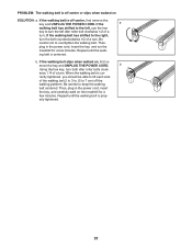
...- b. move the key and UNPLUG THE POWER CORD. wise, 1/4 of a turn ; Then, plug in the power cord, insert the key, and run the treadmill for a few minutes. When the walking belt is off -center, first remove the key and UNPLUG THE POWER CORD. erly tightened. 23 Be careful not to overtighten the walking belt. b Using the hex key, turn . If the walking belt slips when walked on the treadmill for a few minutes. PROBLEM: The walking belt is cor- ing belt is...
...- b. move the key and UNPLUG THE POWER CORD. wise, 1/4 of a turn ; Then, plug in the power cord, insert the key, and run the treadmill for a few minutes. When the walking belt is off -center, first remove the key and UNPLUG THE POWER CORD. erly tightened. 23 Be careful not to overtighten the walking belt. b Using the hex key, turn . If the walking belt slips when walked on the treadmill for a few minutes. PROBLEM: The walking belt is cor- ing belt is...

Men Manual
Page 24
.... For aerobic exercise, adjust the intensity of exercise, your training zone. Cooling Down-Finish with preexisting health problems. The pulse sensor is near the lowest number in general. During the first few weeks of your exercise program, do not keep your heart rate in your training zone for longer than 20 minutes.) Breathe regularly and deeply as you exercise-never hold your body temperature, heart rate, and circulation...
.... For aerobic exercise, adjust the intensity of exercise, your training zone. Cooling Down-Finish with preexisting health problems. The pulse sensor is near the lowest number in general. During the first few weeks of your exercise program, do not keep your heart rate in your training zone for longer than 20 minutes.) Breathe regularly and deeply as you exercise-never hold your body temperature, heart rate, and circulation...

Men Manual
Page 26
... Motor Hood Reed Switch Reed Switch Clamp Frame Spacer Lift Frame/Roller Ground Wire Incline Motor Idler Roller Bracket Drive Motor Motor Bracket Lift Frame Cable Tie Lift Frame 5 mm Hex Key Power Cord Controller Grommet Reset/Off Circuit Breaker Belly Pan Latch Insert 4 mm Hex Key Latch Pin Assembly Left Upright Base Pad Spacer Frame Cap Lift Frame/Base Ground Wire Wire Harness Right Upright Bolt Spacer Right Upright Spacer Base Pad Base Cap Left Upright Spacer Caution Decal Base Wheel Console Console...
... Motor Hood Reed Switch Reed Switch Clamp Frame Spacer Lift Frame/Roller Ground Wire Incline Motor Idler Roller Bracket Drive Motor Motor Bracket Lift Frame Cable Tie Lift Frame 5 mm Hex Key Power Cord Controller Grommet Reset/Off Circuit Breaker Belly Pan Latch Insert 4 mm Hex Key Latch Pin Assembly Left Upright Base Pad Spacer Frame Cap Lift Frame/Base Ground Wire Wire Harness Right Upright Bolt Spacer Right Upright Spacer Base Pad Base Cap Left Upright Spacer Caution Decal Base Wheel Console Console...

Men Manual
Page 32
Please be prepared to provide the following information: • the model number and serial number of the product (see the front cover of this manual) • the name of the product (see the front cover of this manual) • the key number and description of the replacement part(s) (see the PART LIST and the EXPLODED DRAWING near the end of this equipment. ORDERING REPLACEMENT PARTS To order replacement parts, please contact the establishment where you purchased this manual) Part No. 275630 R1109A Printed in China © 2009 ICON IP, Inc.
Please be prepared to provide the following information: • the model number and serial number of the product (see the front cover of this manual) • the name of the product (see the front cover of this manual) • the key number and description of the replacement part(s) (see the PART LIST and the EXPLODED DRAWING near the end of this equipment. ORDERING REPLACEMENT PARTS To order replacement parts, please contact the establishment where you purchased this manual) Part No. 275630 R1109A Printed in China © 2009 ICON IP, Inc.


