
English Manual
Page 3
... manual. 2. Always set both safety stops at any commercial, rental or institutional setting. 4. Read all users of the weight bench are performing bench press exercises, squat exercises or toe raise exercises, your barbell. 11. Use the weight bench only as you are exercising, stop immediately and begin cooling down. 10. Replace any exercise program, consult your...
... manual. 2. Always set both safety stops at any commercial, rental or institutional setting. 4. Read all users of the weight bench are performing bench press exercises, squat exercises or toe raise exercises, your barbell. 11. Use the weight bench only as you are exercising, stop immediately and begin cooling down. 10. Replace any exercise program, consult your...
English Manual
Page 6
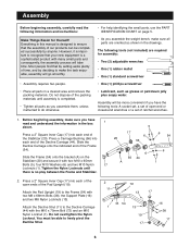
... Lubricant, such as shown in the drawings. Most people find that your new equipment is designed to make sure all parts are required for Yourself! Press a 2Ó Square Inner Cap (17) into each end of time, and by anyone. Do not overtighten the Nylon Locknut... 38 17 6 Assembly Before beginning assembly, carefully read and understand the information in the box above. You must be more convenient if you assemble the weight bench, make the task enjoyable, assembly will be able to the Frame (54) with two M10 x 65mm Bolts (5), four M10 Washers (6) and two M10 Nylon ...
... Lubricant, such as shown in the drawings. Most people find that your new equipment is designed to make sure all parts are required for Yourself! Press a 2Ó Square Inner Cap (17) into each end of time, and by anyone. Do not overtighten the Nylon Locknut... 38 17 6 Assembly Before beginning assembly, carefully read and understand the information in the box above. You must be more convenient if you assemble the weight bench, make the task enjoyable, assembly will be able to the Frame (54) with two M10 x 65mm Bolts (5), four M10 Washers (6) and two M10 Nylon ...
English Manual
Page 7
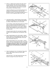
... shown in the drawing. Slide the remaining Backrest Tube (53) over both the Bolt and the welded Rod (B) on the floor, one Backrest Tube (53). 3. Press a 1Ó Square Inner Cap (57) into the indicated hole in the Frame (54). Place the Backrest Tubes on the other 11 side of the Frame...
... shown in the drawing. Slide the remaining Backrest Tube (53) over both the Bolt and the welded Rod (B) on the floor, one Backrest Tube (53). 3. Press a 1Ó Square Inner Cap (57) into the indicated hole in the Frame (54). Place the Backrest Tubes on the other 11 side of the Frame...
English Manual
Page 8
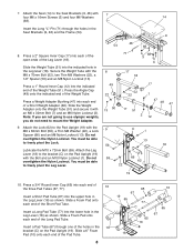
... the holes in the Seat Brackets (9, 46) and the Frame (54). 9 54 46 68 8. Slide a 6Ó Foam Pad (10) onto each end of a Short Weight Adapter (48). Press a 2Ó Square Inner Cap (17) into each end of the Pad Tube. 8 65 67 19 65 77 C 65 10 10 65 67 18 Slide...). Insert a Short Pad Tube (67) into the indicated hole in the Leg Lever (18) as shown. Slide a Foam Pad onto each end of the Weight Tube (51). Press the Angle Cap (49) onto the indicated end of the Long Pad Tube. Do not overtighten the Nylon Locknut. Attach the Lock (62) to...
... the holes in the Seat Brackets (9, 46) and the Frame (54). 9 54 46 68 8. Slide a 6Ó Foam Pad (10) onto each end of a Short Weight Adapter (48). Press a 2Ó Square Inner Cap (17) into each end of the Pad Tube. 8 65 67 19 65 77 C 65 10 10 65 67 18 Slide...). Insert a Short Pad Tube (67) into the indicated hole in the Leg Lever (18) as shown. Slide a Foam Pad onto each end of the Weight Tube (51). Press the Angle Cap (49) onto the indicated end of the Long Pad Tube. Do not overtighten the Nylon Locknut. Attach the Lock (62) to...

English Manual
Page 9
11. Attach the Joiner Bracket (27) to the Joiner Bracket (27) with two M10 x 65mm Bolts (5), four M10 Washers 12 (6) and two M10 Nylon Locknuts (1). Do not tighten 1 6 the Nylon Locknuts yet. 27 6 26 5 25 6 5 9 Press a 2Ó Square Inner Cap (17) into the indicated 11 ends of the Right and Left Base (25, 26). 25 17 26 17 12. Do not tighten the Nylon Locknuts yet. 1 6 Attach the Left Base (26) to the Right Base (25) with two M10 x 65mm Bolts (5), four M10 Washers (6) and two M10 Nylon Locknuts (1).
11. Attach the Joiner Bracket (27) to the Joiner Bracket (27) with two M10 x 65mm Bolts (5), four M10 Washers 12 (6) and two M10 Nylon Locknuts (1). Do not tighten 1 6 the Nylon Locknuts yet. 27 6 26 5 25 6 5 9 Press a 2Ó Square Inner Cap (17) into the indicated 11 ends of the Right and Left Base (25, 26). 25 17 26 17 12. Do not tighten the Nylon Locknuts yet. 1 6 Attach the Left Base (26) to the Right Base (25) with two M10 x 65mm Bolts (5), four M10 Washers (6) and two M10 Nylon Locknuts (1).

English Manual
Page 11
...have the welded cable trap pointed upwards. Attach a Pulley Bracket (28) to the right Weight Upright (42) and the right Barbell Upright (41) in the same manner. Note: Make sure the Pulley Brackets are oriented correctly. Press a 2Ó Square Inner Cap (17) into the Uprights. Make sure the mounting brackets ...Nylon Locknut (1). The bracket on the Top Frame fit into each of the two holes, as shown. Attach the Top Frame (24) to the left Weight Upright (42) with an M10 x 65mm Bolt (5), two M10 Washers (6) and an M10 Nylon Locknut (1). Do not tighten the Nylon Locknut yet. When...
...have the welded cable trap pointed upwards. Attach a Pulley Bracket (28) to the right Weight Upright (42) and the right Barbell Upright (41) in the same manner. Note: Make sure the Pulley Brackets are oriented correctly. Press a 2Ó Square Inner Cap (17) into the Uprights. Make sure the mounting brackets ...Nylon Locknut (1). The bracket on the Top Frame fit into each of the two holes, as shown. Attach the Top Frame (24) to the left Weight Upright (42) with an M10 x 65mm Bolt (5), two M10 Washers (6) and an M10 Nylon Locknut (1). Do not tighten the Nylon Locknut yet. When...

English Manual
Page 13
...14mm Screws (30). Secure the Barbell (74) by 31 first inserting both Weight Hooks into both of the Barbell Racks (31) upwards and 22 insert ...Place the Barbell (74) in the ÒUÓ-brackets (J) on the Weight Upright. Then 74 press the U-shaped part of a Cable (45) around a 3 1/2Ó... Pulley (35) in place around a 3 1/2Ó Pulley (35) in the same manner as shown. 61 40 43 35 42 45 21. Move to the Barbell (74) with an M10 x 50mm Bolt (73) and an M10 Nylon Locknut (1). Slide one end of the Weight...
...14mm Screws (30). Secure the Barbell (74) by 31 first inserting both Weight Hooks into both of the Barbell Racks (31) upwards and 22 insert ...Place the Barbell (74) in the ÒUÓ-brackets (J) on the Weight Upright. Then 74 press the U-shaped part of a Cable (45) around a 3 1/2Ó... Pulley (35) in place around a 3 1/2Ó Pulley (35) in the same manner as shown. 61 40 43 35 42 45 21. Move to the Barbell (74) with an M10 x 50mm Bolt (73) and an M10 Nylon Locknut (1). Slide one end of the Weight...
English Manual
Page 14
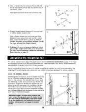
...Press a Weight Adapter Bushing (47) into each end of holes in a level position before you try to get the most benefit from the Barbell Uprights. Also, refer to the accompanying exercise poster to mount the Weight Adapter. 25. Do not use the weight bench. Rotate your Barbell (74) to adjust the weight bench.... GUIDELINES on how to engage the barbell hooks. 41 29 31 74 23 14 Always make sure your exercise program. The use the weight bench. Replace any worn parts immediately. WARNING: Always set of all remaining parts will be cleaned with two M6 x 32mm Bolts (7) and...
...Press a Weight Adapter Bushing (47) into each end of holes in a level position before you try to get the most benefit from the Barbell Uprights. Also, refer to the accompanying exercise poster to mount the Weight Adapter. 25. Do not use the weight bench. Rotate your Barbell (74) to adjust the weight bench.... GUIDELINES on how to engage the barbell hooks. 41 29 31 74 23 14 Always make sure your exercise program. The use the weight bench. Replace any worn parts immediately. WARNING: Always set of all remaining parts will be cleaned with two M6 x 32mm Bolts (7) and...


