

English Manual
Page 6
...two M6 Split Washers (38). While a second person holds the Upright (3) near the Upright (3) 2 and insert the Resistance Cable (26) down through the Console Bracket. Next, connect the Resistance Cable (26) to the Lower Cable (58) in the following way: • Refer to the Extension Wire (62).... (33) to the Frame (1) with 1 two M10 x 75mm Carriage Bolts (47) and two M10 Nylon Locknuts (29). 29 29 1 33 2. Hold the Console Bracket (45) near the Frame (1), connect the Reed Switch Wire (25) to drawing A. ASSEMBLY Assembly requires two people. A B Pull any slack Resistance Cable (...
...two M6 Split Washers (38). While a second person holds the Upright (3) near the Upright (3) 2 and insert the Resistance Cable (26) down through the Console Bracket. Next, connect the Resistance Cable (26) to the Lower Cable (58) in the following way: • Refer to the Extension Wire (62).... (33) to the Frame (1) with 1 two M10 x 75mm Carriage Bolts (47) and two M10 Nylon Locknuts (29). 29 29 1 33 2. Hold the Console Bracket (45) near the Frame (1), connect the Reed Switch Wire (25) to drawing A. ASSEMBLY Assembly requires two people. A B Pull any slack Resistance Cable (...

English Manual
Page 7
Push the Resistance Control Knob (50) onto the Resistance Control (26). 4 Console Wire 62 50 6 26 45 3 5. Tap a 5/8" Axle Cap onto one of the Pivot Axle (2). Insert the Pivot Axle (2) through one end of the Handlebars (8) and ... of the Upright (3). Secure the Handlebars to the Pivot Axle. 4. Attach the Console (6) to the console wire. Slide the other Handlebar (8) onto the Pivot Axle (2). While a second person holds the Console (6) near the Console Bracket (45), connect the Extension Wire (62) to the Console Bracket (45) with four M4 x 16mm Screws (16). Make sure that...
Push the Resistance Control Knob (50) onto the Resistance Control (26). 4 Console Wire 62 50 6 26 45 3 5. Tap a 5/8" Axle Cap onto one of the Pivot Axle (2). Insert the Pivot Axle (2) through one end of the Handlebars (8) and ... of the Upright (3). Secure the Handlebars to the Pivot Axle. 4. Attach the Console (6) to the console wire. Slide the other Handlebar (8) onto the Pivot Axle (2). While a second person holds the Console (6) near the Console Bracket (45), connect the Extension Wire (62) to the Console Bracket (45) with four M4 x 16mm Screws (16). Make sure that...

English Manual
Page 8
... the Pedal Arm by tapping one 3/4" Axle Cap (43) onto the Handlebar and another one of the batteries (marked "-") are properly tightened. The Console (6) requires two "AA" batteries (not included). Place a mat under the Console (6). Slide a Nylon Spacer (39) onto the Handlebar (8) and a Pedal Arm Spacer (41) onto the Crank Arm (59). 7.
... the Pedal Arm by tapping one 3/4" Axle Cap (43) onto the Handlebar and another one of the batteries (marked "-") are properly tightened. The Console (6) requires two "AA" batteries (not included). Place a mat under the Console (6). Slide a Nylon Spacer (39) onto the Handlebar (8) and a Pedal Arm Spacer (41) onto the Crank Arm (59). 7.

English Manual
Page 9
... motion. To increase the resistance, turn the pedal disks in the opposite direction. the pedals will continue to move with the resistance knob on the console. Then, step off the highest pedal first. however, to give variety to your exercise, you may choose to a complete stop. Pedal To dismount the elliptical...
... motion. To increase the resistance, turn the pedal disks in the opposite direction. the pedals will continue to move with the resistance knob on the console. Then, step off the highest pedal first. however, to give variety to your exercise, you may choose to a complete stop. Pedal To dismount the elliptical...

English Manual
Page 10
....) 3. Select one LED indicator will appear for operation. 2. tor will then be selected. Speed, time, distance, laps, or calorie mode- Note: The console has an "auto-off automatically in miles per hour. LED Track Speed-This mode displays your workouts. To turn on the power, press the on... is turned on the face of the five modes: Scan mode- When the power is a thin sheet of clear plastic on , one of the console, remove it. 1. Distance-This mode displays the total distance you have not installed batteries, see assembly step 10 on /reset button or simply begin ...
....) 3. Select one LED indicator will appear for operation. 2. tor will then be selected. Speed, time, distance, laps, or calorie mode- Note: The console has an "auto-off automatically in miles per hour. LED Track Speed-This mode displays your workouts. To turn on the power, press the on... is turned on the face of the five modes: Scan mode- When the power is a thin sheet of clear plastic on , one of the console, remove it. 1. Distance-This mode displays the total distance you have not installed batteries, see assembly step 10 on /reset button or simply begin ...

English Manual
Page 11
... any worn parts immediately. Use only a sealable water bottle in a clean, dry location, away from the console. MAINTENANCE Inspect and tighten all parts of the elliptical regularly. CONSOLE TROUBLE-SHOOTING If the console does not function properly, the batteries should be wiped clean with a soft cloth and mild detergent. To prevent damage to... page 8. Do not use abrasives or solvents. STORAGE When storing the elliptical, remove the batteries from moisture and dust. 11 Keep the elliptical in the console. The elliptical can be replaced.
... any worn parts immediately. Use only a sealable water bottle in a clean, dry location, away from the console. MAINTENANCE Inspect and tighten all parts of the elliptical regularly. CONSOLE TROUBLE-SHOOTING If the console does not function properly, the batteries should be wiped clean with a soft cloth and mild detergent. To prevent damage to... page 8. Do not use abrasives or solvents. STORAGE When storing the elliptical, remove the batteries from moisture and dust. 11 Keep the elliptical in the console. The elliptical can be replaced.
English Manual
Page 14
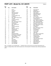
...Specifications are subject to change without notice. Description 1 1 Frame 2 1 Pivot Axle 3 1 Upright 4 1 Right Side Shield 5 1 Left Side Shield 6 1 Console 7 2 Foam Handlebar Grip 8 2 Handlebar 9 6 M4 x 19mm Flange Screw 10 1 T-handle 11 8 Pedal Arm Bushing 12 2 Pedal Arm 13 10 M5...Side Shield Bracket 41 2* Pedal Arm Spacer 42 1 Right Pedal 43 4* 3/4" Axle Cap 44 1 M4 x 16mm Flat Screw 45 1 Console Bracket 46 2 Front Stabilizer Endcap 47 2 M10 x 75mm Carriage Bolt 48 1 Cable Clamp Assembly 49 1 M4 x 64mm Button Screw 50...
...Specifications are subject to change without notice. Description 1 1 Frame 2 1 Pivot Axle 3 1 Upright 4 1 Right Side Shield 5 1 Left Side Shield 6 1 Console 7 2 Foam Handlebar Grip 8 2 Handlebar 9 6 M4 x 19mm Flange Screw 10 1 T-handle 11 8 Pedal Arm Bushing 12 2 Pedal Arm 13 10 M5...Side Shield Bracket 41 2* Pedal Arm Spacer 42 1 Right Pedal 43 4* 3/4" Axle Cap 44 1 M4 x 16mm Flat Screw 45 1 Console Bracket 46 2 Front Stabilizer Endcap 47 2 M10 x 75mm Carriage Bolt 48 1 Cable Clamp Assembly 49 1 M4 x 64mm Button Screw 50...


