
Canadian English Manual
Page 2
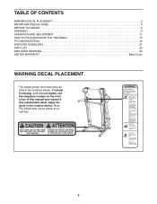
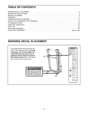
TABLE OF CONTENTS WARNING DECAL PLACEMENT 2 IMPORTANT PRECAUTIONS 3 BEFORE YOU BEGIN 5 ASSEMBLY 6 OPERATION AND ADJUSTMENT 11 HOW TO FOLD AND MOVE THE TREADMILL 17 TROUBLESHOOTING 18 EXERCISE GUIDELINES 21 PART LIST 22 EXPLODED DRAWING 24 LIMITED WARRANTY Back Cover WARNING DECAL PLACEMENT The decals shown here have been ...
TABLE OF CONTENTS WARNING DECAL PLACEMENT 2 IMPORTANT PRECAUTIONS 3 BEFORE YOU BEGIN 5 ASSEMBLY 6 OPERATION AND ADJUSTMENT 11 HOW TO FOLD AND MOVE THE TREADMILL 17 TROUBLESHOOTING 18 EXERCISE GUIDELINES 21 PART LIST 22 EXPLODED DRAWING 24 LIMITED WARRANTY Back Cover WARNING DECAL PLACEMENT The decals shown here have been ...

Canadian English Manual
Page 4
... kg) to do so by an authorized service representative only. 26. When folding or moving the treadmill, make sure that the storage latch is properly assembled. (See ASSEMBLY on page 6, and HOW TO FOLD AND MOVE THE TREADMILL on page 17.) You must be performed by an authorized ser- Inspect and properly tighten all...
... kg) to do so by an authorized service representative only. 26. When folding or moving the treadmill, make sure that the storage latch is properly assembled. (See ASSEMBLY on page 6, and HOW TO FOLD AND MOVE THE TREADMILL on page 17.) You must be performed by an authorized ser- Inspect and properly tighten all...

Canadian English Manual
Page 6
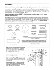
... number of the part, from the PART LIST near the end of the treadmill walking belt is not in the Base, and use power tools for assembly. Make sure that the treadmill is a normal condition and does not affect treadmill performance. Assembly requires the included hex key and your own Phillips screwdriver adjustable wrench . , and...
... number of the part, from the PART LIST near the end of the treadmill walking belt is not in the Base, and use power tools for assembly. Make sure that the treadmill is a normal condition and does not affect treadmill performance. Assembly requires the included hex key and your own Phillips screwdriver adjustable wrench . , and...

Canadian English Manual
Page 9
...x 19mm Screws (1). do not, turn one connector and try again. Remove the wire tie from the Upright Wire (77) and console wire. 8 Console Assembly Connect the Upright Wire (77) to avoid scratching the Console. 7. Insert the console wire into the large hole in the location shown. Start all four...), which has a large hole in the Right Handrail (90) and out of them . Attach the Right Handrail with an M4 x 13mm Screw (3). Set the console assembly on a soft surface to the console wire. Tighten the four M10 x 96mm Bolts (5). 9 89 6 10 9 6 73 6 90 10 10 6 78 Make sure...
...x 19mm Screws (1). do not, turn one connector and try again. Remove the wire tie from the Upright Wire (77) and console wire. 8 Console Assembly Connect the Upright Wire (77) to avoid scratching the Console. 7. Insert the console wire into the large hole in the location shown. Start all four...), which has a large hole in the Right Handrail (90) and out of them . Attach the Right Handrail with an M4 x 13mm Screw (3). Set the console assembly on a soft surface to the console wire. Tighten the four M10 x 96mm Bolts (5). 9 89 6 10 9 6 73 6 90 10 10 6 78 Make sure...

Canadian English Manual
Page 22
... Bracket Cable Tie Lift Frame Filter Wire Power Cord Controller Grommet Reset/Off Circuit Breaker Belly Pan Latch Insert Left Crosswalk Arm Latch Pin Assembly Left Upright Insert Screw Crosswalk Arm Insert Right Crosswalk Arm Upright Wire Right Upright Bolt Spacer Right Upright Spacer Base Pad Base Endcap Left Upright Spacer Caution Decal Base...
... Bracket Cable Tie Lift Frame Filter Wire Power Cord Controller Grommet Reset/Off Circuit Breaker Belly Pan Latch Insert Left Crosswalk Arm Latch Pin Assembly Left Upright Insert Screw Crosswalk Arm Insert Right Crosswalk Arm Upright Wire Right Upright Bolt Spacer Right Upright Spacer Base Pad Base Endcap Left Upright Spacer Caution Decal Base...
English Manual
Page 1
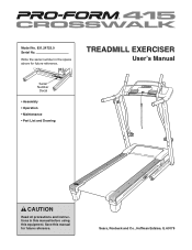
Save this equipment. Write the serial number in this manual before using this manual for future reference. Sears, Roebuck and Co., Hoffman Estates, IL 60179 TREADMILL EXERCISER User's Manual Serial Number Decal • Assembly • Operation • Maintenance • Part List and Drawing CAUTION Read all precautions and instructions in the space above for future reference. Model No. 831.24723.0 Serial No.
Save this equipment. Write the serial number in this manual before using this manual for future reference. Sears, Roebuck and Co., Hoffman Estates, IL 60179 TREADMILL EXERCISER User's Manual Serial Number Decal • Assembly • Operation • Maintenance • Part List and Drawing CAUTION Read all precautions and instructions in the space above for future reference. Model No. 831.24723.0 Serial No.
English Manual
Page 2
If a decal is missing, or if it is not legible, call 1-888-533-1333 and order a free replacement decal. Note: The decals may not be shown at actual size. 2 TABLE OF CONTENTS WARNING DECAL PLACEMENT 2 IMPORTANT PRECAUTIONS 3 BEFORE YOU BEGIN 5 ASSEMBLY 6 OPERATION AND ADJUSTMENT 11 HOW TO FOLD AND MOVE THE TREADMILL 17 TROUBLESHOOTING 18 EXERCISE GUIDELINES 21 PART LIST 22 EXPLODED DRAWING 24 90 DAY FULL WARRANTY Back Cover WARNING DECAL PLACEMENT The decals shown here have been applied in the location shown. Apply the decal in the locations shown.
If a decal is missing, or if it is not legible, call 1-888-533-1333 and order a free replacement decal. Note: The decals may not be shown at actual size. 2 TABLE OF CONTENTS WARNING DECAL PLACEMENT 2 IMPORTANT PRECAUTIONS 3 BEFORE YOU BEGIN 5 ASSEMBLY 6 OPERATION AND ADJUSTMENT 11 HOW TO FOLD AND MOVE THE TREADMILL 17 TROUBLESHOOTING 18 EXERCISE GUIDELINES 21 PART LIST 22 EXPLODED DRAWING 24 90 DAY FULL WARRANTY Back Cover WARNING DECAL PLACEMENT The decals shown here have been applied in the location shown. Apply the decal in the locations shown.
English Manual
Page 4
Do not attempt to raise, lower, or move the treadmill. 22. This treadmill is properly assembled. (See ASSEMBLY on page 6, and HOW TO FOLD AND MOVE THE TREADMILL on page 17.) You must be performed by an authorized ser- Inspect and properly tighten all parts of the circuit breaker.) 21. DANGER: 25. less ...
Do not attempt to raise, lower, or move the treadmill. 22. This treadmill is properly assembled. (See ASSEMBLY on page 6, and HOW TO FOLD AND MOVE THE TREADMILL on page 17.) You must be performed by an authorized ser- Inspect and properly tighten all parts of the circuit breaker.) 21. DANGER: 25. less ...
English Manual
Page 6
... 25mm Screw (2)-4 M4 x 19mm Screw (1)-6 M8 x 25mm Bolt (6)-4 1/4" Washer (9)-4 1/4" x 3 1/2" Bolt (4)-4 Bolt Spacer (79)-4 M10 x 96mm Bolt (5)-4 1. Assembly requires the included hex keys , your own Phillips screwdriver adjustable wrench . , and an Use the drawings below each drawing is preattached to one of the... Upright Wire (77) to the top of this manual. Assembly requires two persons. Set the treadmill in the parts bag, check to be assembled. Attach a Base Pad (81) to identify the assembly hardware. The number after the parentheses is unplugged. If there...
... 25mm Screw (2)-4 M4 x 19mm Screw (1)-6 M8 x 25mm Bolt (6)-4 1/4" Washer (9)-4 1/4" x 3 1/2" Bolt (4)-4 Bolt Spacer (79)-4 M10 x 96mm Bolt (5)-4 1. Assembly requires the included hex keys , your own Phillips screwdriver adjustable wrench . , and an Use the drawings below each drawing is preattached to one of the... Upright Wire (77) to the top of this manual. Assembly requires two persons. Set the treadmill in the parts bag, check to be assembled. Attach a Base Pad (81) to identify the assembly hardware. The number after the parentheses is unplugged. If there...

English Manual
Page 9
... (not shown). Tighten the four M10 x 96mm Bolts (5). 9 89 6 10 6 73 6 90 10 10 6 78 9 Have a second person hold the console assembly near the Right Upright (78). The connectors should slide together easily and snap into the Right Upright (78). Make sure that no wires are pinched.... 8 77 Console Assembly Console Wire 78 77 9. Remove the wire tie from the Upright Wire (77) and console wire. Finger tighten two M8 x 25mm Bolts (6) ...
... (not shown). Tighten the four M10 x 96mm Bolts (5). 9 89 6 10 6 73 6 90 10 10 6 78 9 Have a second person hold the console assembly near the Right Upright (78). The connectors should slide together easily and snap into the Right Upright (78). Make sure that no wires are pinched.... 8 77 Console Assembly Console Wire 78 77 9. Remove the wire tie from the Upright Wire (77) and console wire. Finger tighten two M8 x 25mm Bolts (6) ...

English Manual
Page 22
... Motor Bracket Cable Tie Lift Frame Filter Wire Power Cord Controller Grommet Reset/Off Switch Belly Pan Latch Insert Left Crosswalk Arm Latch Pin Assembly Left Upright Insert Screw Crosswalk Arm Insert Right Crosswalk Arm Upright Wire Right Upright Bolt Spacer Right Upright Spacer Base Pad Base Endcap Left Upright Spacer Caution Decal Base...
... Motor Bracket Cable Tie Lift Frame Filter Wire Power Cord Controller Grommet Reset/Off Switch Belly Pan Latch Insert Left Crosswalk Arm Latch Pin Assembly Left Upright Insert Screw Crosswalk Arm Insert Right Crosswalk Arm Upright Wire Right Upright Bolt Spacer Right Upright Spacer Base Pad Base Endcap Left Upright Spacer Caution Decal Base...


