
English Manual
Page 2
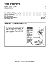
... shown at actual size. PROFORM is missing or illegible, see the front cover of this manual and request a free replacement decal. Apply the decal in the location shown. TABLE OF CONTENTS WARNING DECAL PLACEMENT 2 IMPORTANT PRECAUTIONS 3 BEFORE YOU BEGIN 4 PART IDENTIFICATION CHART 5 ASSEMBLY 6 HOW TO USE THE ELLIPTICAL 15 MAINTENANCE AND TROUBLESHOOTING 26...
... shown at actual size. PROFORM is missing or illegible, see the front cover of this manual and request a free replacement decal. Apply the decal in the location shown. TABLE OF CONTENTS WARNING DECAL PLACEMENT 2 IMPORTANT PRECAUTIONS 3 BEFORE YOU BEGIN 4 PART IDENTIFICATION CHART 5 ASSEMBLY 6 HOW TO USE THE ELLIPTICAL 15 MAINTENANCE AND TROUBLESHOOTING 26...
English Manual
Page 5
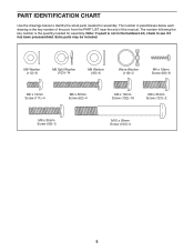
Extra parts may be included. PART IDENTIFICATION CHART Use the drawings below each drawing is the quantity needed for assembly. M6 Washer (112)–-8 M8 Split Washer (103)–-14 M8 Washer (95)–-6 Wave Washer (118)–-2 M4 x 19mm Screw (80)–-8 M6 x 12mm Screw (111)–-4 M6 x 50mm Screw (62)&#... in parentheses below to see if it has been preassembled. The number in the hardware kit, check to identify the small parts needed for assembly. The number following the key number is the key number of the part, from the PART LIST near the end of this manual.
Extra parts may be included. PART IDENTIFICATION CHART Use the drawings below each drawing is the quantity needed for assembly. M6 Washer (112)–-8 M8 Split Washer (103)–-14 M8 Washer (95)–-6 Wave Washer (118)–-2 M4 x 19mm Screw (80)–-8 M6 x 12mm Screw (111)–-4 M6 x 50mm Screw (62)&#... in parentheses below to see if it has been preassembled. The number in the hardware kit, check to identify the small parts needed for assembly. The number following the key number is the key number of the part, from the PART LIST near the end of this manual.
English Manual
Page 6
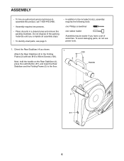
... Latch Button (67), and lower the Rear Stabilizer and the Folding Frame (2) to the included tool(s), assembly requires the following tools: one Phillips screwdriver one rubber mallet Assembly may be easier if you have a set of wrenches. To avoid damaging parts, do not use power... tools. 1. ASSEMBLY •• To hire an authorized service technician to assemble this product, call 1-800-445-2480. •• Assembly requires two persons. •• Place all assembly steps. •• To identify small parts, see page 5. &#...
... Latch Button (67), and lower the Rear Stabilizer and the Folding Frame (2) to the included tool(s), assembly requires the following tools: one Phillips screwdriver one rubber mallet Assembly may be easier if you have a set of wrenches. To avoid damaging parts, do not use power... tools. 1. ASSEMBLY •• To hire an authorized service technician to assemble this product, call 1-800-445-2480. •• Assembly requires two persons. •• Place all assembly steps. •• To identify small parts, see page 5. &#...
English Manual
Page 9
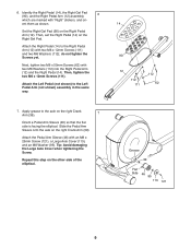
Then, set the Right Pedal (14) on the other side of the elliptical. Then, tighten the two M6 x 12mm Screws (111). Repeat this step on the Right ...axle on the right Crank Arm (39). 7 Orient a Pedal Arm Sleeve (46) so that the flat side is facing the elliptical. Attach the Pedal Arm Sleeve (46) with two M6 x 12mm Screws (111) and two M6 Washers (112); Set the Right... the Large Axle Cover when tightening the Screw. Apply grease to the Left Pedal Arm (not shown) assembly in the same way. 14 90 12 112 111 112 62 7. ent them as shown. do not tighten the Screws yet. 6. Identify...
Then, set the Right Pedal (14) on the other side of the elliptical. Then, tighten the two M6 x 12mm Screws (111). Repeat this step on the Right ...axle on the right Crank Arm (39). 7 Orient a Pedal Arm Sleeve (46) so that the flat side is facing the elliptical. Attach the Pedal Arm Sleeve (46) with two M6 x 12mm Screws (111) and two M6 Washers (112); Set the Right... the Large Axle Cover when tightening the Screw. Apply grease to the Left Pedal Arm (not shown) assembly in the same way. 14 90 12 112 111 112 62 7. ent them as shown. do not tighten the Screws yet. 6. Identify...
English Manual
Page 14
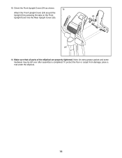
Note: An extra grease packet and some hardware may be left over after assembly is completed. To protect the floor or carpet from damage, place a mat under the elliptical. 14 Make sure that all parts of the elliptical are properly tightened. 15. Orient the Front Upright Cover (24) as shown. 15 Attach the Front Upright Cover (24) around the Upright (5) by pressing the tabs on the Front 24 Upright Cover into the Rear Upright Cover (25). 25 5 16.
Note: An extra grease packet and some hardware may be left over after assembly is completed. To protect the floor or carpet from damage, place a mat under the elliptical. 14 Make sure that all parts of the elliptical are properly tightened. 15. Orient the Front Upright Cover (24) as shown. 15 Attach the Front Upright Cover (24) around the Upright (5) by pressing the tabs on the Front 24 Upright Cover into the Rear Upright Cover (25). 25 5 16.

English Manual
Page 32
... replacement parts, see the back cover of this manual. *These parts are subject to change without notice. Description Key No. Description 101 2 102 16 103 14 104 2 105 2 106 15 107 4 108 6 109 8 110 2 111 4 112 8 113 2 114 2 115 1 116 1 117 1 118 2 119 1 120 1 121 2 122 1 123 1 124 1 125 1 126 2 Small... Screw Left Lift Arm Right Lift Arm Left Link Arm Motor Power Wire Harness #6 x 3/8" Screw M10 x 14mm Washer Blue Wire White Wire User’'s Manual Assembly Tool Grease Packet Note: Specifications are not illustrated. 32 Key No.
... replacement parts, see the back cover of this manual. *These parts are subject to change without notice. Description Key No. Description 101 2 102 16 103 14 104 2 105 2 106 15 107 4 108 6 109 8 110 2 111 4 112 8 113 2 114 2 115 1 116 1 117 1 118 2 119 1 120 1 121 2 122 1 123 1 124 1 125 1 126 2 Small... Screw Left Lift Arm Right Lift Arm Left Link Arm Motor Power Wire Harness #6 x 3/8" Screw M10 x 14mm Washer Blue Wire White Wire User’'s Manual Assembly Tool Grease Packet Note: Specifications are not illustrated. 32 Key No.


