
English Manual
Page 1
... Sat. 8 a.m.-12 p.m. CAUTION Read all precautions and instructions in the space above for future reference. USER'S MANUAL MT Please do not contact the store. Serial Number Decal ACTIVATE YOUR WARRANTY To register your product and activate your warranty today, go to www.proformservice.com/ registration. Or call 1-888-533-1333 Mon.-Fri. 6 a.m.-6 p.m. Keep this equipment. www.proform.com Model No.
... Sat. 8 a.m.-12 p.m. CAUTION Read all precautions and instructions in the space above for future reference. USER'S MANUAL MT Please do not contact the store. Serial Number Decal ACTIVATE YOUR WARRANTY To register your product and activate your warranty today, go to www.proformservice.com/ registration. Or call 1-888-533-1333 Mon.-Fri. 6 a.m.-6 p.m. Keep this equipment. www.proform.com Model No.
English Manual
Page 2
... PLACEMENT 2 IMPORTANT PRECAUTIONS 3 BEFORE YOU BEGIN 5 PART IDENTIFICATION CHART 6 ASSEMBLY 7 HOW TO USE THE EXERCISE BIKE 13 FCC INFORMATION 18 MAINTENANCE AND TROUBLESHOOTING 19 EXERCISE GUIDELINES 21 PART LIST 22 EXPLODED DRAWING 23 ORDERING REPLACEMENT PARTS Back Cover LIMITED WARRANTY Back Cover WARNING DECAL PLACEMENT This drawing shows the location(s) of this manual and request a free replacement decal. If a decal is a registered trademark of ICON Health & Fitness, Inc. 2 PROFORM is missing or illegible, see the front...
... PLACEMENT 2 IMPORTANT PRECAUTIONS 3 BEFORE YOU BEGIN 5 PART IDENTIFICATION CHART 6 ASSEMBLY 7 HOW TO USE THE EXERCISE BIKE 13 FCC INFORMATION 18 MAINTENANCE AND TROUBLESHOOTING 19 EXERCISE GUIDELINES 21 PART LIST 22 EXPLODED DRAWING 23 ORDERING REPLACEMENT PARTS Back Cover LIMITED WARRANTY Back Cover WARNING DECAL PLACEMENT This drawing shows the location(s) of this manual and request a free replacement decal. If a decal is a registered trademark of ICON Health & Fitness, Inc. 2 PROFORM is missing or illegible, see the front...
English Manual
Page 3
.... This is used by someone responsible for home use by persons with pre-existing health problems. 3. Place the exercise bike on your exercise bike before using the exercise bike; Inspect and properly tighten all parts each time the exercise bike is especially important for use only. Various factors, including the user's movement, may result in general. 15. Reduce your exercise bike. Use the exercise bike only as an exercise aid in determining heart rate trends in...
.... This is used by someone responsible for home use by persons with pre-existing health problems. 3. Place the exercise bike on your exercise bike before using the exercise bike; Inspect and properly tighten all parts each time the exercise bike is especially important for use only. Various factors, including the user's movement, may result in general. 15. Reduce your exercise bike. Use the exercise bike only as an exercise aid in determining heart rate trends in...
English Manual
Page 5
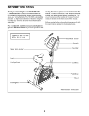
... the body. Length: 2 ft. 8 in the drawing below. For your workouts at home more effective and enjoyable. To help us . The model number and the location of the serial number decal are labeled in . (81 cm) Width: 2 ft. (61 cm) Water Bottle Holder* Heart Rate Monitor Console Handlebar Seat Carriage Knob Seat Knob Leveling Foot Pedal/Strap Wheel *Water bottle is an effective exercise for selecting the new PROFORM® 135 CSX exercise bike...
... the body. Length: 2 ft. 8 in the drawing below. For your workouts at home more effective and enjoyable. To help us . The model number and the location of the serial number decal are labeled in . (81 cm) Width: 2 ft. (61 cm) Water Bottle Holder* Heart Rate Monitor Console Handlebar Seat Carriage Knob Seat Knob Leveling Foot Pedal/Strap Wheel *Water bottle is an effective exercise for selecting the new PROFORM® 135 CSX exercise bike...
English Manual
Page 6
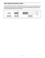
PART IDENTIFICATION CHART Use the drawings below each drawing is the key number of the part, from the PART LIST near the end of this manual. Note: If a part is the quantity needed for assembly. The number following the key number is not in parentheses below to see if it has been preassembled. Extra parts may be included. M4 x 12mm Screw (57)-6 M8 x 18mm Screw (42)-8 M10 x 68mm Screw (44)-4 6 The number in the hardware kit, check to identify the small parts needed for assembly.
PART IDENTIFICATION CHART Use the drawings below each drawing is the key number of the part, from the PART LIST near the end of this manual. Note: If a part is the quantity needed for assembly. The number following the key number is not in parentheses below to see if it has been preassembled. Extra parts may be included. M4 x 12mm Screw (57)-6 M8 x 18mm Screw (42)-8 M10 x 68mm Screw (44)-4 6 The number in the hardware kit, check to identify the small parts needed for assembly.
English Manual
Page 7
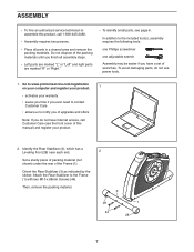
... a set of wrenches. Attach the Rear Stabilizer to the included tool(s), assembly requires the following tools: one Phillips screwdriver one adjustable wrench Assembly may be easier if you finish all parts in a cleared area and remove the packing materials. ASSEMBLY • To hire an authorized service technician to assemble this manual) and register your warranty • saves you time if you ever need...
... a set of wrenches. Attach the Rear Stabilizer to the included tool(s), assembly requires the following tools: one Phillips screwdriver one adjustable wrench Assembly may be easier if you finish all parts in a cleared area and remove the packing materials. ASSEMBLY • To hire an authorized service technician to assemble this manual) and register your warranty • saves you time if you ever need...

English Manual
Page 9
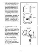
... the Upright (4), and connect them . 6 Avoid pinching the Pulse Wire (58) 6 58 42 4 42 42 9 Tip: Avoid pinching the Pulse Wire (58). Orient the Rear and Front Upright Covers (19, 20) as shown. 5. Then, press the Rear and Front Upright Covers (19, 20) downward onto the Left and Right Shields (21, 22). 19 57 57 20 4 21, 22 6. start all the Screws, and then tighten them...
... the Upright (4), and connect them . 6 Avoid pinching the Pulse Wire (58) 6 58 42 4 42 42 9 Tip: Avoid pinching the Pulse Wire (58). Orient the Rear and Front Upright Covers (19, 20) as shown. 5. Then, press the Rear and Front Upright Covers (19, 20) downward onto the Left and Right Shields (21, 22). 19 57 57 20 4 21, 22 6. start all the Screws, and then tighten them...
English Manual
Page 10
7. Otherwise, you insert batteries. To purchase an optional power adapter, call the telephone number on the cover of the power adapter into the receptacle on the Console (5); Plug one end of this manual. While a second person holds the Console (5) near the Upright (4), plug the Main Wire (41) and the Pulse Wire (58) into the Upright (4). Attach the Console (5) to orient the batteries as shown by the diagrams inside the battery compartments. IMPORTANT: If...
7. Otherwise, you insert batteries. To purchase an optional power adapter, call the telephone number on the cover of the power adapter into the receptacle on the Console (5); Plug one end of this manual. While a second person holds the Console (5) near the Upright (4), plug the Main Wire (41) and the Pulse Wire (58) into the Upright (4). Attach the Console (5) to orient the batteries as shown by the diagrams inside the battery compartments. IMPORTANT: If...
English Manual
Page 12
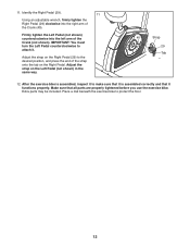
After the exercise bike is assembled correctly and that all parts are properly tightened before you use the exercise bike. Identify the Right Pedal (29). 11 Using an adjustable wrench, firmly tighten the Right Pedal (29) clockwise into the left arm of the Crank (40). Place a mat beneath the exercise bike to the desired position, and press the end of the strap onto the tab on the Right Pedal. Make sure...
After the exercise bike is assembled correctly and that all parts are properly tightened before you use the exercise bike. Identify the Right Pedal (29). 11 Using an adjustable wrench, firmly tighten the Right Pedal (29) clockwise into the left arm of the Crank (40). Place a mat beneath the exercise bike to the desired position, and press the end of the strap onto the tab on the Right Pedal. Make sure...
English Manual
Page 13
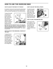
... press the ends of the adjustment holes in one or both of the seat, first loosen the carriage knob a few turns. Then, tighten the post knob. Then, move the seat forward or backward to make sure that the post knob is engaged in the seat post. Leveling Feet To adjust the horizontal position of the leveling feet under the rear stabilizer until the exercise bike...
... press the ends of the adjustment holes in one or both of the seat, first loosen the carriage knob a few turns. Then, tighten the post knob. Then, move the seat forward or backward to make sure that the post knob is engaged in the seat post. Leveling Feet To adjust the horizontal position of the leveling feet under the rear stabilizer until the exercise bike...
English Manual
Page 14
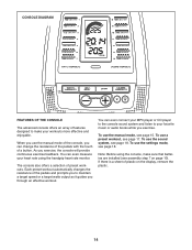
... your heart rate using the console, make your favorite music or audio books while you exercise, the console will provide continuous exercise feedback. To use the manual mode, see page 18. To use the manual mode of preset workouts. CONSOLE DIAGRAM FEATURES OF THE CONSOLE The advanced console offers an array of features designed to maintain a target speed or a target watts output as it guides you can change the resistance of the pedals with...
... your heart rate using the console, make your favorite music or audio books while you exercise, the console will provide continuous exercise feedback. To use the manual mode, see page 18. To use the manual mode of preset workouts. CONSOLE DIAGRAM FEATURES OF THE CONSOLE The advanced console offers an array of features designed to maintain a target speed or a target watts output as it guides you can change the resistance of the pedals with...
English Manual
Page 15
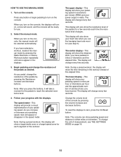
... and decrease buttons. This display will turn on page 18. 15 The display will be selected automatically. HOW TO USE THE MANUAL MODE 1. Press any button or begin pedaling to turn on the console, the manual mode will be ready for use the handgrip heart rate monitor (see THE SETTINGS MODE on , a tone will sound, and the console will change the resistance of the pedals for a few seconds. If you press the buttons, it will change every...
... and decrease buttons. This display will turn on page 18. 15 The display will be selected automatically. HOW TO USE THE MANUAL MODE 1. Press any button or begin pedaling to turn on the console, the manual mode will be ready for use the handgrip heart rate monitor (see THE SETTINGS MODE on , a tone will sound, and the console will change the resistance of the pedals for a few seconds. If you press the buttons, it will change every...
English Manual
Page 16
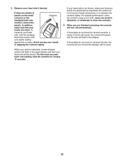
... most accurate heart rate reading, hold the handgrip heart rate monitor with your hands are finished exercising, the console will turn off automatically. When you are positioned as described. If your heart rate is detected, a heart-shaped symbol will turn off and the displays will be reset. To measure your heart rate, hold the contacts for at least 15 seconds. 16 If the pedals do not move your...
... most accurate heart rate reading, hold the handgrip heart rate monitor with your hands are finished exercising, the console will turn off automatically. When you are positioned as described. If your heart rate is detected, a heart-shaped symbol will turn off and the displays will be reset. To measure your heart rate, hold the contacts for at least 15 seconds. 16 If the pedals do not move your...
English Manual
Page 17
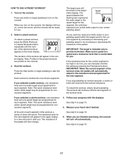
... Start the workout. Press the Start button or begin pedaling to alert you turn on the console, the displays will turn on the console. If you selected a calorie workout, one resistance level and one watts target are finished exercising, the console will continue until the number of the preset workouts are programmed for the next segment. Measure your pedaling speed or by increasing or decreasing your heart rate if desired. The Zone space...
... Start the workout. Press the Start button or begin pedaling to alert you turn on the console, the displays will turn on the console. If you selected a calorie workout, one resistance level and one watts target are finished exercising, the console will continue until the number of the preset workouts are programmed for the next segment. Measure your pedaling speed or by increasing or decreasing your heart rate if desired. The Zone space...
English Manual
Page 18
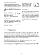
... display will show pedaling speed and distance in accordance with the limits for the console and to 3.5 mm male audio cable (not included) into the jack on the console and into a jack on your MP3 player, CD player, or other personal audio player; To select the settings mode, press and hold down the Watts Workouts button until the settings mode information appears in . Next, press the play music or audio...
... display will show pedaling speed and distance in accordance with the limits for the console and to 3.5 mm male audio cable (not included) into the jack on the console and into a jack on your MP3 player, CD player, or other personal audio player; To select the settings mode, press and hold down the Watts Workouts button until the settings mode information appears in . Next, press the play music or audio...
English Manual
Page 19
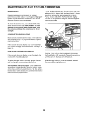
... Screws (57), and then remove the Rear and Front Upright Covers. Turn the Crank (40) until the console displays correct feedback. When the reed switch is aligned with the Reed Switch. MAINTENANCE AND TROUBLESHOOTING MAINTENANCE Regular maintenance is important for battery replacement instructions. CONSOLE TROUBLESHOOTING Most console problems are the result of mild soap. HOW TO ADJUST THE REED SWITCH If the console does not display correct feedback, the reed switch should be adjusted. Replace any worn parts immediately. To clean the exercise bike, use the handgrip heart rate...
... Screws (57), and then remove the Rear and Front Upright Covers. Turn the Crank (40) until the console displays correct feedback. When the reed switch is aligned with the Reed Switch. MAINTENANCE AND TROUBLESHOOTING MAINTENANCE Regular maintenance is important for battery replacement instructions. CONSOLE TROUBLESHOOTING Most console problems are the result of mild soap. HOW TO ADJUST THE REED SWITCH If the console does not display correct feedback, the reed switch should be adjusted. Replace any worn parts immediately. To clean the exercise bike, use the handgrip heart rate...
English Manual
Page 20
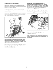
... edge of the Post Cover (16) and remove it outward, and remove the Seat Post (10). Then, gently remove the Right Shield. To adjust the drive belt, you remove from each hole. Then, using an adjustable wrench, remove the Post Knob. HOW TO ADJUST THE DRIVE BELT If the pedals slip while you are two sizes of screws in the shields-note which size of screw you must remove the parts described below. Identify...
... edge of the Post Cover (16) and remove it outward, and remove the Seat Post (10). Then, gently remove the Right Shield. To adjust the drive belt, you remove from each hole. Then, using an adjustable wrench, remove the Post Knob. HOW TO ADJUST THE DRIVE BELT If the pedals slip while you are two sizes of screws in the shields-note which size of screw you must remove the parts described below. Identify...
English Manual
Page 21
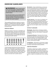
... nutrition and adequate rest are rounded off to strengthen your body uses carbohydrate calories for fat burning and aerobic exercise. Cooling Down-Finish with 5 to five workouts each week, with pre-existing health problems. The heart rate monitor is activity that requires large amounts of your exercise program, do not keep your heart rate in your goal is to achieving results. This is...
... nutrition and adequate rest are rounded off to strengthen your body uses carbohydrate calories for fat burning and aerobic exercise. Cooling Down-Finish with 5 to five workouts each week, with pre-existing health problems. The heart rate monitor is activity that requires large amounts of your exercise program, do not keep your heart rate in your goal is to achieving results. This is...
English Manual
Page 22
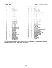
... 2 Shield Cover 25 2 Crank Cover 26 2 Rear Stabilizer Cap 27 2 Wheel Cap 28 2 Leveling Foot 29 1 Right Pedal/Strap 30 1 Left Pedal/Strap 31 1 Eddy Mechanism 32 1 Idler 33 1 Resistance Motor 34 1 Resistance Cable 35 1 Reed Switch/Wire 36 2 M4 x 16mm Flange Screw 37 1 Clamp 38 1 Crank Bearing Assembly 39 2 Magnet 40 1 Crank/Pulley 41 1 Main Wire 42 8 M8 x 18mm Screw 43 2 Clip 44 4 M10 x 68mm Screw 45 1 Idler Screw 46 1 Pivot Screw 47 1 Adjustment Screw 48...
... 2 Shield Cover 25 2 Crank Cover 26 2 Rear Stabilizer Cap 27 2 Wheel Cap 28 2 Leveling Foot 29 1 Right Pedal/Strap 30 1 Left Pedal/Strap 31 1 Eddy Mechanism 32 1 Idler 33 1 Resistance Motor 34 1 Resistance Cable 35 1 Reed Switch/Wire 36 2 M4 x 16mm Flange Screw 37 1 Clamp 38 1 Crank Bearing Assembly 39 2 Magnet 40 1 Crank/Pulley 41 1 Main Wire 42 8 M8 x 18mm Screw 43 2 Clip 44 4 M10 x 68mm Screw 45 1 Idler Screw 46 1 Pivot Screw 47 1 Adjustment Screw 48...
English Manual
Page 24
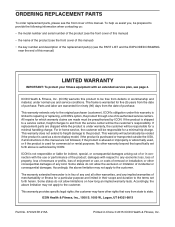
... product (see the front cover of this manual) • the key number and description of the replacement part(s) (see the PART LIST and the EXPLODED DRAWING near the end of this manual. All repairs for which warranty claims are made must be the customer's responsibility. The warranty extended hereunder is in lieu of removal or installation; Accordingly, the above limitation may not apply to any...
... product (see the front cover of this manual) • the key number and description of the replacement part(s) (see the PART LIST and the EXPLODED DRAWING near the end of this manual. All repairs for which warranty claims are made must be the customer's responsibility. The warranty extended hereunder is in lieu of removal or installation; Accordingly, the above limitation may not apply to any...


