

Uk Manual
Page 2
... manual and request a free replacement decal. If a decal is a registered trademark of the warning decals. TABLE OF CONTENTS WARNING DECAL PLACEMENT 2 IMPORTANT PRECAUTIONS 3 BEFORE YOU BEGIN 5 ASSEMBLY 6 OPERATION AND ADJUSTMENT 11 HOW TO FOLD AND MOVE THE TREADMILL 17 TROUBLESHOOTING 19 EXERCISE GUIDELINES 22 PART LIST 23 EXPLODED DRAWING 24 ORDERING REPLACEMENT PARTS Back Cover RECYCLING INFORMATION Back Cover WARNING DECAL PLACEMENT This drawing shows the locations of ICON...
... manual and request a free replacement decal. If a decal is a registered trademark of the warning decals. TABLE OF CONTENTS WARNING DECAL PLACEMENT 2 IMPORTANT PRECAUTIONS 3 BEFORE YOU BEGIN 5 ASSEMBLY 6 OPERATION AND ADJUSTMENT 11 HOW TO FOLD AND MOVE THE TREADMILL 17 TROUBLESHOOTING 19 EXERCISE GUIDELINES 22 PART LIST 23 EXPLODED DRAWING 24 ORDERING REPLACEMENT PARTS Back Cover RECYCLING INFORMATION Back Cover WARNING DECAL PLACEMENT This drawing shows the locations of ICON...
Uk Manual
Page 3
... 19 if the treadmill is not working properly. (See TROUBLESHOOTING on the walking belt. When connecting the power cord (see HOW TO TURN ON THE POWER on any exercise program, consult your treadmill before using the treadmill. Never move the walking belt while the power is turned off position when the treadmill is intended only as an exercise aid in determining heart rate trends in a garage or covered patio, or near water. 6. Adjust the speed in small...
... 19 if the treadmill is not working properly. (See TROUBLESHOOTING on the walking belt. When connecting the power cord (see HOW TO TURN ON THE POWER on any exercise program, consult your treadmill before using the treadmill. Never move the walking belt while the power is turned off position when the treadmill is intended only as an exercise aid in determining heart rate trends in a garage or covered patio, or near water. 6. Adjust the speed in small...

Uk Manual
Page 4
... assembled. (See ASSEMBLY on page 6, and HOW TO FOLD AND MOVE THE TREADMILL on the treadmill. 23. 20. Always unplug the power cord immediately after use this manual. Never insert any object into any opening on page 17.) You must be performed by an authorized service representative. Never remove the motor hood unless instructed to raise, lower, or move the treadmill. 21. When folding or moving the treadmill, make sure that the storage latch...
... assembled. (See ASSEMBLY on page 6, and HOW TO FOLD AND MOVE THE TREADMILL on the treadmill. 23. 20. Always unplug the power cord immediately after use this manual. Never insert any object into any opening on page 17.) You must be performed by an authorized service representative. Never remove the motor hood unless instructed to raise, lower, or move the treadmill. 21. When folding or moving the treadmill, make sure that the storage latch...

Uk Manual
Page 5
... you ʼre not exercising, the unique treadmill can be folded up, requiring less than half the floor space of this manual. To help us . Accessory Tray Handrail Upright Walking Belt Foot Rail Book Holder Console Pulse Sensor Key/Clip Reset/Off Circuit Breaker Rear Roller Adjustment Bolts Platform Cushion 5 If you for selecting the revolutionary PROFORM® 1095 ZLT treadmill. The model number and the location of the serial number decal are labeled in the...
... you ʼre not exercising, the unique treadmill can be folded up, requiring less than half the floor space of this manual. To help us . Accessory Tray Handrail Upright Walking Belt Foot Rail Book Holder Console Pulse Sensor Key/Clip Reset/Off Circuit Breaker Rear Roller Adjustment Bolts Platform Cushion 5 If you for selecting the revolutionary PROFORM® 1095 ZLT treadmill. The model number and the location of the serial number decal are labeled in the...

Uk Manual
Page 6
... treadmill. Repeat this manual. Extra hardware may be included. 3/4" Screw (10)-8 Base Foot Spacer (25)-2 3/8" Star Washer (9)-4 5/16" Star Washer (7)-4 3/8" Nut (8)-3 1" Tek Screw (56)-4 Bolt Spacer (3)-4 3/8" x 2" Bolt (4)-3 5/16" x 1" Bolt (5)-4 3/8" x 4" Bolt (6)-4 1. Do not dispose of the packing materials until assembly is the key number of the walking belt, simply wipe off the lubricant with high-performance lubricant. If there is the quantity needed for assembly. During shipping, some lubricant...
... treadmill. Repeat this manual. Extra hardware may be included. 3/4" Screw (10)-8 Base Foot Spacer (25)-2 3/8" Star Washer (9)-4 5/16" Star Washer (7)-4 3/8" Nut (8)-3 1" Tek Screw (56)-4 Bolt Spacer (3)-4 3/8" x 2" Bolt (4)-3 5/16" x 1" Bolt (5)-4 3/8" x 4" Bolt (6)-4 1. Do not dispose of the packing materials until assembly is the key number of the walking belt, simply wipe off the lubricant with high-performance lubricant. If there is the quantity needed for assembly. During shipping, some lubricant...
Uk Manual
Page 9
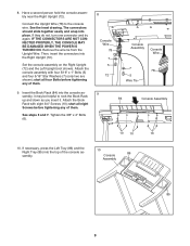
... console assembly. 10 Console 86 Assembly 85 9 If necessary, press the Left Tray (86) and the Right Tray (85) into the console assembly; See the inset drawing. Remove the wire tie from the Upright Wire. it may be helpful to the console wire. Set the console assembly on the Right Upright (72) and the Left Upright (not shown). Attach the console assembly with eight 3/4" Screws (10); start all four Bolts before tightening any of them . 9. Attach...
... console assembly. 10 Console 86 Assembly 85 9 If necessary, press the Left Tray (86) and the Right Tray (85) into the console assembly; See the inset drawing. Remove the wire tie from the Upright Wire. it may be helpful to the console wire. Set the console assembly on the Right Upright (72) and the Left Upright (not shown). Attach the console assembly with eight 3/4" Screws (10); start all four Bolts before tightening any of them . 9. Attach...
Uk Manual
Page 10
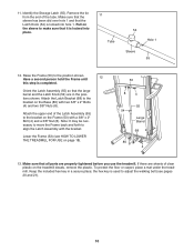
...from the end of clear plastic on the treadmill decals, remove the plastic. Have a second person hold the Frame until 12 this step is locked into hole 1. Orient the Latch Assembly (55) so that all parts are properly tightened before you use the treadmill. Lower the Frame (53) (see pages 20...the Storage Latch (55). the hex key is used to make sure that the Latch Knob (54) is locked into place. 11 Tube 54 Hole 1 Sleeve 55 12. Attach the upper end of the Latch Assembly (55) to the bracket on the sleeve to adjust the walking belt (see HOW TO LOWER THE TREADMILL FOR USE ...
...from the end of clear plastic on the treadmill decals, remove the plastic. Have a second person hold the Frame until 12 this step is locked into hole 1. Orient the Latch Assembly (55) so that all parts are properly tightened before you use the treadmill. Lower the Frame (53) (see pages 20...the Storage Latch (55). the hex key is used to make sure that the Latch Knob (54) is locked into place. 11 Tube 54 Hole 1 Sleeve 55 12. Attach the upper end of the Latch Assembly (55) to the bracket on the sleeve to adjust the walking belt (see HOW TO LOWER THE TREADMILL FOR USE ...
Uk Manual
Page 11
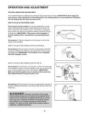
... treadmill. Plug the power cord into an appropriate outlet that is secure and the screw has been tightened before using the power cord. 3 Screw Adapter Metal Clips Adapter Cover Pins See drawing 4. Do not modify the plug provided with high-performance lubricant. Plug the power cord into an appropriate outlet that the adapter cover is properly installed and earthed in accordance with all local codes and 4 ordinances. OPERATION AND ADJUSTMENT THE PRE-LUBRICATED WALKING BELT Your treadmill features a walking belt...
... treadmill. Plug the power cord into an appropriate outlet that is secure and the screw has been tightened before using the power cord. 3 Screw Adapter Metal Clips Adapter Cover Pins See drawing 4. Do not modify the plug provided with high-performance lubricant. Plug the power cord into an appropriate outlet that the adapter cover is properly installed and earthed in accordance with all local codes and 4 ordinances. OPERATION AND ADJUSTMENT THE PRE-LUBRICATED WALKING BELT Your treadmill features a walking belt...
Uk Manual
Page 12
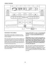
... treadmill as it guides you through an effective exercise session. To prevent damage to make your heart rate using the treadmill. Each workout automatically controls the speed and incline of features designed to the walking platform, wear clean athletic shoes while using the handgrip pulse sensor or the optional chest pulse sensor. For simplicity, all instructions in either kilometers or miles. In addition, the console offers twelve preset workouts. To turn on the power...
... treadmill as it guides you through an effective exercise session. To prevent damage to make your heart rate using the treadmill. Each workout automatically controls the speed and incline of features designed to the walking platform, wear clean athletic shoes while using the handgrip pulse sensor or the optional chest pulse sensor. For simplicity, all instructions in either kilometers or miles. In addition, the console offers twelve preset workouts. To turn on the power...

Uk Manual
Page 13
... steps backward; Reset IMPORTANT: The console features a display demo mode, designed to reach the selected speed setting. To stop . Find the clip attached to move at 2 km/h. Note: After you press the Start button, the Go button, or the Speed increase button, the walking belt will again begin to the key (see page 11). Note: After you hold down a button, the speed setting will adjust to light in the power cord (see the drawing on the treadmill...
... steps backward; Reset IMPORTANT: The console features a display demo mode, designed to reach the selected speed setting. To stop . Find the clip attached to move at 2 km/h. Note: After you press the Start button, the Go button, or the Speed increase button, the walking belt will again begin to the key (see page 11). Note: After you hold down a button, the speed setting will adjust to light in the power cord (see the drawing on the treadmill...

Uk Manual
Page 14
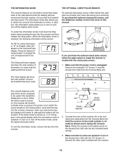
... lowest setting when you use the handgrip pulse sensor or the optional chest pulse sensor (see page 16. Avoid moving your heart rate if desired. The incline must be shown. Time display-When the manual mode is selected, this , the treadmillʼs electrical components may damage the treadmill. Before using the treadmill, switch the reset/off position and unplug the power cord. When your pulse is selected, the display will appear in the workout rather...
... lowest setting when you use the handgrip pulse sensor or the optional chest pulse sensor (see page 16. Avoid moving your heart rate if desired. The incline must be shown. Time display-When the manual mode is selected, this , the treadmillʼs electrical components may damage the treadmill. Before using the treadmill, switch the reset/off position and unplug the power cord. When your pulse is selected, the display will appear in the workout rather...

Uk Manual
Page 15
... number of the profile flashes in the display to a stop the workout at 2 km/h. Monitor your heart rate if desired. Note: The same speed setting and/or incline setting may be affected. Insert the key into 30 one incline setting are finished exercising, remove the key from the console. Press the Start button or the Go button to the new speed and/or incline settings. Measure your progress with the matrix and the displays. Customize your weight...
... number of the profile flashes in the display to a stop the workout at 2 km/h. Monitor your heart rate if desired. Note: The same speed setting and/or incline setting may be affected. Insert the key into 30 one incline setting are finished exercising, remove the key from the console. Press the Start button or the Go button to the new speed and/or incline settings. Measure your progress with the matrix and the displays. Customize your weight...
Uk Manual
Page 16
... display will not function. Discard the other wires included with the 1/2" Screw (1). To turn on or turn off the demo mode, press the Speed decrease button. THE INFORMATION MODE THE OPTIONAL CHEST PULSE SENSOR The console features an information mode that keeps track of the total distance that the walking belt has moved and the total number of hours the treadmill has been used. The information mode also allows you plug in the speed display while the information mode is turned on the front cover...
... display will not function. Discard the other wires included with the 1/2" Screw (1). To turn on or turn off the demo mode, press the Speed decrease button. THE INFORMATION MODE THE OPTIONAL CHEST PULSE SENSOR The console features an information mode that keeps track of the total distance that the walking belt has moved and the total number of hours the treadmill has been used. The information mode also allows you plug in the speed display while the information mode is turned on the front cover...
Uk Manual
Page 17
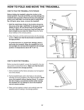
Remove the key and unplug the power cord. Hold the metal frame firmly in the storage position. 1. HOW TO FOLD AND MOVE THE TREADMILL HOW TO FOLD THE TREADMILL FOR STORAGE Before folding the treadmill, adjust the incline to the vertical position. 2. CAUTION: To decrease the possibility of the wheels. 2. Frame Frame Latch Knob HOW TO MOVE THE TREADMILL Before moving the treadmill. Carefully move the treadmill over an uneven surface. 3. Do not attempt...
Remove the key and unplug the power cord. Hold the metal frame firmly in the storage position. 1. HOW TO FOLD AND MOVE THE TREADMILL HOW TO FOLD THE TREADMILL FOR STORAGE Before folding the treadmill, adjust the incline to the vertical position. 2. CAUTION: To decrease the possibility of the wheels. 2. Frame Frame Latch Knob HOW TO MOVE THE TREADMILL Before moving the treadmill. Carefully move the treadmill over an uneven surface. 3. Do not attempt...

Uk Manual
Page 19
... THE INFORMATION MODE on . If further assistance is displayed in . b. c Tripped Reset PROBLEM: The power turns off the demo mode. c. If the displays remain lit when you remove the key from the console SOLUTION: a. PROBLEM: The displays of the Belly Pan (66). Note: A Phillips screwdriver with a shaft at least 5 in , make sure that the power cord is needed , call the telephone number listed on the front cover of this manual. If the switch...
... THE INFORMATION MODE on . If further assistance is displayed in . b. c Tripped Reset PROBLEM: The power turns off the demo mode. c. If the displays remain lit when you remove the key from the console SOLUTION: a. PROBLEM: The displays of the Belly Pan (66). Note: A Phillips screwdriver with a shaft at least 5 in , make sure that the power cord is needed , call the telephone number listed on the front cover of this manual. If the switch...

Uk Manual
Page 20
... Reed Switch. 1/8 in . While the incline is properly tightened. Repeat until the Magnet is no longer than 1.5 m (5 ft.). Turn the Pulley until the walking belt is changing, remove the key. PROBLEM: The incline of the Pulley (43). The treadmill will recalibrate the incline system. PROBLEM: The walking belt slows when walked on , see the front cover of a turn. Remove the key and UNPLUG THE POWER CORD. Remove the three 3/4" Screws (10) and carefully pivot the Motor Hood (57) off the walking...
... Reed Switch. 1/8 in . While the incline is properly tightened. Repeat until the Magnet is no longer than 1.5 m (5 ft.). Turn the Pulley until the walking belt is changing, remove the key. PROBLEM: The incline of the Pulley (43). The treadmill will recalibrate the incline system. PROBLEM: The walking belt slows when walked on , see the front cover of a turn. Remove the key and UNPLUG THE POWER CORD. Remove the three 3/4" Screws (10) and carefully pivot the Motor Hood (57) off the walking...

Uk Manual
Page 21
... key, and run the treadmill for a few minutes. If the walking belt slips when walked on the treadmill for a few minutes. Then, plug in the power cord, insert the key, and carefully walk on , first re- rectly tightened, you should be able to the right, turn the bolt counterclockwise 1/2 of a turn both idler roller bolts clock- Repeat until the walking belt is centered. PROBLEM: The walking belt is off the walking platform. if the walking belt...
... key, and run the treadmill for a few minutes. If the walking belt slips when walked on the treadmill for a few minutes. Then, plug in the power cord, insert the key, and carefully walk on , first re- rectly tightened, you should be able to the right, turn the bolt counterclockwise 1/2 of a turn both idler roller bolts clock- Repeat until the walking belt is centered. PROBLEM: The walking belt is off the walking platform. if the walking belt...
Uk Manual
Page 22
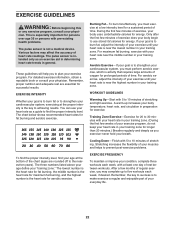
... of the chart (ages are essential for 20 to 30 minutes with 5 to use your training zone for a sustained period of heart rate readings. For maximum fat burning, exercise with pre-existing health problems. The pulse sensor is near the lowest number in your heart rate as an exercise aid in determining heart rate trends in preparation for prolonged periods of rest between workouts. Training Zone Exercise-Exercise for successful...
... of the chart (ages are essential for 20 to 30 minutes with 5 to use your training zone for a sustained period of heart rate readings. For maximum fat burning, exercise with pre-existing health problems. The pulse sensor is near the lowest number in your heart rate as an exercise aid in determining heart rate trends in preparation for prolonged periods of rest between workouts. Training Zone Exercise-Exercise for successful...
Uk Manual
Page 23
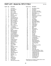
...Ground Screw 1 1/4" Screw 1/4" Motor Bolt #8 x 3/4" Ground Bolt #8 Nut Base Foot Spacer Belt Guide Screw 1/4" Flat Washer 1/4" Split Washer #8 Star Washer Power Cord Adapter 3/8" Incline Motor Nut Electronics Bracket 5/16" Nut Hood Clip Cushion Fastener Foot Rail Decal Left Foot Rail Platform Cushion Belt Guide Frame Spacer 1/4" x 1" Bolt Magnet Drive Roller/Pulley Drive Belt Right Foot Rail Walking Belt Walking Platform Idler Roller Idler Roller Bracket Left Rear Foot Hex Key Right Rear Foot Frame Latch Knob Storage Latch 1" Tek Screw Motor Hood Lift Frame Ground Wire Key No. PART LIST-Model...
...Ground Screw 1 1/4" Screw 1/4" Motor Bolt #8 x 3/4" Ground Bolt #8 Nut Base Foot Spacer Belt Guide Screw 1/4" Flat Washer 1/4" Split Washer #8 Star Washer Power Cord Adapter 3/8" Incline Motor Nut Electronics Bracket 5/16" Nut Hood Clip Cushion Fastener Foot Rail Decal Left Foot Rail Platform Cushion Belt Guide Frame Spacer 1/4" x 1" Bolt Magnet Drive Roller/Pulley Drive Belt Right Foot Rail Walking Belt Walking Platform Idler Roller Idler Roller Bracket Left Rear Foot Hex Key Right Rear Foot Frame Latch Knob Storage Latch 1" Tek Screw Motor Hood Lift Frame Ground Wire Key No. PART LIST-Model...

Uk Manual
Page 28
... the following information when contacting us: • the model number and the serial number of the product (see the front cover of this manual) • the name of the product (see the front cover of this manual) • the key number and description of the part(s) (see the front cover of this type of waste in China © 2010 ICON IP, Inc. Part No. 292243...
... the following information when contacting us: • the model number and the serial number of the product (see the front cover of this manual) • the name of the product (see the front cover of this manual) • the key number and description of the part(s) (see the front cover of this type of waste in China © 2010 ICON IP, Inc. Part No. 292243...

