
Owner's Manual
Page 1
Operating Instructions AUDIO/VIDEO MULTI-CHANNEL RECEIVER VSX-81TXV VSX-81TXV-S Register your product at www.pioneerelectronics.com (US) www.pioneerelectronics.ca (Canada) • Protect your new investment The details of your ...purchase will be on file for reference in the event of an insurance claim such as loss or theft. • Receive free tips, updates and service bulletins on your new product • Improve product development Your input helps us continue to design products that meet your...
Operating Instructions AUDIO/VIDEO MULTI-CHANNEL RECEIVER VSX-81TXV VSX-81TXV-S Register your product at www.pioneerelectronics.com (US) www.pioneerelectronics.ca (Canada) • Protect your new investment The details of your ...purchase will be on file for reference in the event of an insurance claim such as loss or theft. • Receive free tips, updates and service bulletins on your new product • Improve product development Your input helps us continue to design products that meet your...
Owner's Manual
Page 2
...-S Responsible Party Name: PIONEER ELECTRONICS SERVICE INC. This equipment generates, uses, and can be determined by turning the equipment off and on this equipment does cause harmful interference to radio or television reception, which the receiver is no guarantee that ...of the following two conditions: (1) This device may not cause harmful interference, and (2) this device must accept any interference received, including interference that may cause undesired operation. and Australia Model C67-7-3_En ATTENTION - D1-4-2-1_En FEDERAL COMMUNICATIONS DECLARATION OF CONFORMITY ...
...-S Responsible Party Name: PIONEER ELECTRONICS SERVICE INC. This equipment generates, uses, and can be determined by turning the equipment off and on this equipment does cause harmful interference to radio or television reception, which the receiver is no guarantee that ...of the following two conditions: (1) This device may not cause harmful interference, and (2) this device must accept any interference received, including interference that may cause undesired operation. and Australia Model C67-7-3_En ATTENTION - D1-4-2-1_En FEDERAL COMMUNICATIONS DECLARATION OF CONFORMITY ...
Owner's Manual
Page 4
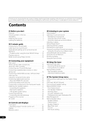
... making cable connections 12 About the video converter 12 Connecting your TV and DVD player 13 Connecting a satellite/cable receiver or other set-top box 13 Connecting a DVD/HDD recorder, VCR and other video sources 14 Using the component... Placing the speakers 18 THX speaker system setup 19 Connecting antennas 19 Connecting external antennas 20 Plugging in the receiver 20 AC outlet 20 04 Controls and displays Front panel 21 Operating range of remote control unit 22 Display ...27 Using the Advanced surround effects 27 Listening in a safe place for buying this Pioneer product.
... making cable connections 12 About the video converter 12 Connecting your TV and DVD player 13 Connecting a satellite/cable receiver or other set-top box 13 Connecting a DVD/HDD recorder, VCR and other video sources 14 Using the component... Placing the speakers 18 THX speaker system setup 19 Connecting antennas 19 Connecting external antennas 20 Plugging in the receiver 20 AC outlet 20 04 Controls and displays Front panel 21 Operating range of remote control unit 22 Display ...27 Using the Advanced surround effects 27 Listening in a safe place for buying this Pioneer product.
Owner's Manual
Page 5
...Settings The Input Setup menu 58 Input function default and possible settings 58 The Other Setup menu 59 Multi-Room and IR receiver setup 59 SR+ Setup for Pioneer plasma displays 59 OSD Adjustment 60 Erasing one of the remote control button settings . . 66 Resetting the remote control ... formats 79 Stream direct with different input signal formats . . . 81 Specifications 82 Cleaning the unit 82 10 Using other functions Setting the AV options 61 Making an audio or a video recording 62 Reducing the level of your system settings 63 Resetting the system 63 Default system settings...
...Settings The Input Setup menu 58 Input function default and possible settings 58 The Other Setup menu 59 Multi-Room and IR receiver setup 59 SR+ Setup for Pioneer plasma displays 59 OSD Adjustment 60 Erasing one of the remote control button settings . . 66 Resetting the remote control ... formats 79 Stream direct with different input signal formats . . . 81 Specifications 82 Cleaning the unit 82 10 Using other functions Setting the AV options 61 Making an audio or a video recording 62 Reducing the level of your system settings 63 Resetting the system 63 Default system settings...
Owner's Manual
Page 6
... surround sound, including a special LFE (Low Frequency Effects) channel for optimal surround sound. • THX Select2 certified design This receiver bears the THX Select2 logo, which includes the advanced features of Professional Acoustic Calibration EQ. 01 Before you start Chapter 1: Before ...you start Features • Advanced Direct Energy design This receiver offers a new advancement in discrete design unique to Pioneer for any stereo source. With the additional benefits of numerous MCACC preset memories, standing wave control and ...
... surround sound, including a special LFE (Low Frequency Effects) channel for optimal surround sound. • THX Select2 certified design This receiver bears the THX Select2 logo, which includes the advanced features of Professional Acoustic Calibration EQ. 01 Before you start Chapter 1: Before ...you start Features • Advanced Direct Energy design This receiver offers a new advancement in discrete design unique to Pioneer for any stereo source. With the additional benefits of numerous MCACC preset memories, standing wave control and ...
Owner's Manual
Page 7
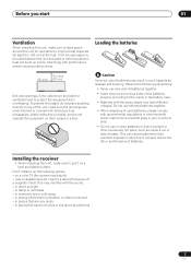
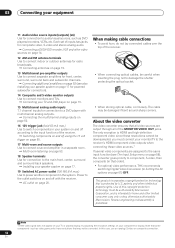
...blocked or covered with items (such as leakage and bursting. in places that apply in places that gives off a magnetic field). Installing the receiver • When installing this unit, make sure to leave space around the unit for ventilation and to protect the equipment from overheating. in ...extremely hot or cold areas - in direct sunlight - Loading the batteries 8 inches Receiver (20 cm) Slot and openings in . (20 cm) at the top). To prevent fire hazard, do not operate the equipment on a color TV...
...blocked or covered with items (such as leakage and bursting. in places that apply in places that gives off a magnetic field). Installing the receiver • When installing this unit, make sure to leave space around the unit for ventilation and to protect the equipment from overheating. in ...extremely hot or cold areas - in direct sunlight - Loading the batteries 8 inches Receiver (20 cm) Slot and openings in . (20 cm) at the top). To prevent fire hazard, do not operate the equipment on a color TV...
Owner's Manual
Page 8
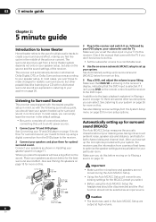
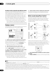
... Automatically setting up using the Auto MCACC Setup the headphones should be selected as shown below for more on the sound. This receiver will overwrite any existing settings for the best surround sound effect. In addition to the basic playback explained in the Auto MCACC Setup... input on your liking. After you have set up the microphone provided with the following quick setup guide, you can simply leave the receiver in the receiver's display, indicating that came with multichannel surround sound) are not moved during the Auto MCACC Setup. Front Left (L) Subwoofer (SW) ...
... Automatically setting up using the Auto MCACC Setup the headphones should be selected as shown below for more on the sound. This receiver will overwrite any existing settings for the best surround sound effect. In addition to the basic playback explained in the Auto MCACC Setup... input on your liking. After you have set up the microphone provided with the following quick setup guide, you can simply leave the receiver in the receiver's display, indicating that came with multichannel surround sound) are not moved during the Auto MCACC Setup. Front Left (L) Subwoofer (SW) ...
Owner's Manual
Page 9
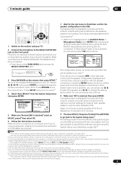
...ear level at any time to be farther than the actual distance from the MCACC Data Check screen. 5 minute guide 02 RECEIVER INPUT SELECT SYSTEM OFF SOURCE AV PRE-PROGRAMMED AND LEARNING REMOTE CONTROL UNIT CD DVD DVR 2 TV DVR1 TVCTRL CD-R/TAPE iPod HDMI2 HDMI1 XM RADIO TUNER ...ROOM 2 RECEIVER SR+ DIMMER DIALOG E S.RETRIEVER MIDNIGHT/ LOUDNESS D.ACCESS +10 AV PARAMETER TOP MENU TUNE DTVMENU ST SETUP ENTER CLASS DISC ENTER CH LEVEL MENU ST T.EDIT RETURN TUNE GUIDE CATEGORY...
...ear level at any time to be farther than the actual distance from the MCACC Data Check screen. 5 minute guide 02 RECEIVER INPUT SELECT SYSTEM OFF SOURCE AV PRE-PROGRAMMED AND LEARNING REMOTE CONTROL UNIT CD DVD DVR 2 TV DVR1 TVCTRL CD-R/TAPE iPod HDMI2 HDMI1 XM RADIO TUNER ...ROOM 2 RECEIVER SR+ DIMMER DIALOG E S.RETRIEVER MIDNIGHT/ LOUDNESS D.ACCESS +10 AV PARAMETER TOP MENU TUNE DTVMENU ST SETUP ENTER CLASS DISC ENTER CH LEVEL MENU ST T.EDIT RETURN TUNE GUIDE CATEGORY...
Owner's Manual
Page 10
... TV so that the VIDEO 1 input is coming from the speakers connected to this seems to play. RECEIVER INPUT SELECT SYSTEM OFF SOURCE GUIDE TV CONTROL TV VOL INPUT SELECT TV CH VOL AV PRE-PROGRAMMED AND LEARNING REMOTE CONTROL UNIT DTV ON/OFF MPX REC DTVINFO MUTE REC STOP JUKEBOX CD... DVD DVR 2 TV DVR1 TVCTRL CD-R/TAPE HDMI2 XM RADIO ROOM 2 iPod HDMI1 TUNER RECEIVER SLEEP VIDEO SEL ANALOG ATT AUDIO SUBTITLE HDD DISP...
... TV so that the VIDEO 1 input is coming from the speakers connected to this seems to play. RECEIVER INPUT SELECT SYSTEM OFF SOURCE GUIDE TV CONTROL TV VOL INPUT SELECT TV CH VOL AV PRE-PROGRAMMED AND LEARNING REMOTE CONTROL UNIT DTV ON/OFF MPX REC DTVINFO MUTE REC STOP JUKEBOX CD... DVD DVR 2 TV DVR1 TVCTRL CD-R/TAPE HDMI2 XM RADIO ROOM 2 iPod HDMI1 TUNER RECEIVER SLEEP VIDEO SEL ANALOG ATT AUDIO SUBTITLE HDD DISP...
Owner's Manual
Page 11
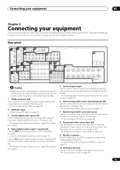
... Setup menu on page 46. 11 En Connecting your equipment 03 Chapter 3 Connecting your equipment This receiver provides you can control all your equipment from the power outlet. Operating other Pioneer components so that has component video output, such as CD players, tape decks, turntables, etc.... Connecting an IR receiver on page 70. 6 Stereo analog audio source inputs/(outputs) (x3) Use for example. ...
... Setup menu on page 46. 11 En Connecting your equipment 03 Chapter 3 Connecting your equipment This receiver provides you can control all your equipment from the power outlet. Operating other Pioneer components so that has component video output, such as CD players, tape decks, turntables, etc.... Connecting an IR receiver on page 70. 6 Stereo analog audio source inputs/(outputs) (x3) Use for example. ...
Owner's Manual
Page 12
...Corporation, and is intended for home and other intellectual property rights. Reverse engineering or disassembly is protected by Macrovision. Each set of the receiver. • When connecting optical cables, be converted. Connecting additional amplifiers on page 52 (see The Input Setup menu on page 58),...components in your TV and DVD player on page 19. 13 Multichannel pre-amplifier outputs Use to power another component in Setting the AV options on page 20. This product incorporates copyright protection technology that some components (such as DVD players/recorders, VCRs, etc. ...
...Corporation, and is intended for home and other intellectual property rights. Reverse engineering or disassembly is protected by Macrovision. Each set of the receiver. • When connecting optical cables, be converted. Connecting additional amplifiers on page 52 (see The Input Setup menu on page 58),...components in your TV and DVD player on page 19. 13 Multichannel pre-amplifier outputs Use to power another component in Setting the AV options on page 20. This product incorporates copyright protection technology that some components (such as DVD players/recorders, VCRs, etc. ...
Owner's Manual
Page 13
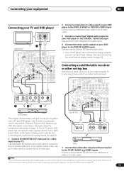
...CENTER L IN 3 R SUB R SUR- VIDEO S-VIDEO IN IN 3 Connect a coaxial-type1 digital audio output on page 50. DIGITAL OUT R AUDIO L VIDEO AV OUT S-VIDEO 1 Connect the MONITOR OUT video jack to a video input on your DVD player has multichannel analog outputs, you set -top box to the... player 4 Connect the stereo audio outputs on your DVD player offers multichannel analog audio outputs, see The Input Setup menu on this receiver together with a TV and DVD player, with S-video or composite video connections. Connect using a stereo RCA/phono jack cable and a video or S-...
...CENTER L IN 3 R SUB R SUR- VIDEO S-VIDEO IN IN 3 Connect a coaxial-type1 digital audio output on page 50. DIGITAL OUT R AUDIO L VIDEO AV OUT S-VIDEO 1 Connect the MONITOR OUT video jack to a video input on your DVD player has multichannel analog outputs, you set -top box to the... player 4 Connect the stereo audio outputs on your DVD player offers multichannel analog audio outputs, see The Input Setup menu on this receiver together with a TV and DVD player, with S-video or composite video connections. Connect using a stereo RCA/phono jack cable and a video or S-...
Owner's Manual
Page 14
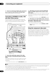
... to the OPTICAL 1 (DVR/VCR1) input. See the manuals that came with your video component doesn't have a digital audio output, you can skip this receiver using a coaxial digital audio cable. VSX-81TXV IN 1 DIGITAL OPTICAL MULTI-ROOM & SOURCE ROOM 2(ZONE 2) OUT IR IN ANTENNA OUT IN 1 IN 2... should give superior picture quality when compared to the DVR/VCR1 AUDIO and VIDEO inputs. OPTICAL COAXIAL DIGITAL OUT 3 R AUDIO L VIDEO AV IN S-VIDEO R AUDIO L AV OUT VIDEO S-VIDEO 12 DVR, VCR, etc. 1 Connect the audio/video outputs of the coaxial inputs on page 58). 14 En ...
... to the OPTICAL 1 (DVR/VCR1) input. See the manuals that came with your video component doesn't have a digital audio output, you can skip this receiver using a coaxial digital audio cable. VSX-81TXV IN 1 DIGITAL OPTICAL MULTI-ROOM & SOURCE ROOM 2(ZONE 2) OUT IR IN ANTENNA OUT IN 1 IN 2... should give superior picture quality when compared to the DVR/VCR1 AUDIO and VIDEO inputs. OPTICAL COAXIAL DIGITAL OUT 3 R AUDIO L VIDEO AV IN S-VIDEO R AUDIO L AV OUT VIDEO S-VIDEO 12 DVR, VCR, etc. 1 Connect the audio/video outputs of the coaxial inputs on page 58). 14 En ...
Owner's Manual
Page 15
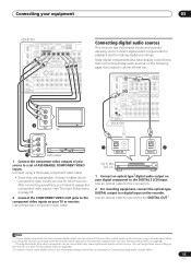
... too. Most digital components also have analog connections. Connect using a coaxial cable. After connecting everything, you'll need to tell the receiver which source. Use an optical cable to connect to the DIGITAL OUT.2 Note 1 • If your TV or monitor. Use an...FRONT WOOFER OUT IN MONITOR OUT OUT IN L DVR/VCR2 R FRONT MULTI C Y PB PR 2 COMPONENT VIDEO TV Connecting digital audio sources This receiver has both digital inputs and outputs, allowing you must make analog connections as explained in Connecting analog audio sources below. 15 En Use a three-way...
... too. Most digital components also have analog connections. Connect using a coaxial cable. After connecting everything, you'll need to tell the receiver which source. Use an optical cable to connect to the DIGITAL OUT.2 Note 1 • If your TV or monitor. Use an...FRONT WOOFER OUT IN MONITOR OUT OUT IN L DVR/VCR2 R FRONT MULTI C Y PB PR 2 COMPONENT VIDEO TV Connecting digital audio sources This receiver has both digital inputs and outputs, allowing you must make analog connections as explained in Connecting analog audio sources below. 15 En Use a three-way...
Owner's Manual
Page 16
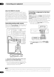
... WMA9 Pro-encoded audio using a coaxial or optical digital connection when connected to the analog audio inputs on the recorder. S- Connecting analog audio sources This receiver features two stereo audio-only inputs. VIDEO VIDEO/GAME INPUT VIDEO L AUDIO R DIGITAL IN MCACC SETUP MIC VIDEO/AUDIO OUTPUT DIGITAL OUT TV game, video...
... WMA9 Pro-encoded audio using a coaxial or optical digital connection when connected to the analog audio inputs on the recorder. S- Connecting analog audio sources This receiver features two stereo audio-only inputs. VIDEO VIDEO/GAME INPUT VIDEO L AUDIO R DIGITAL IN MCACC SETUP MIC VIDEO/AUDIO OUTPUT DIGITAL OUT TV game, video...
Owner's Manual
Page 17
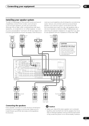
...Switching the speaker impedance on page 63 if you like (it may cause the power to match these up with an impedance of the receiver's surround sound capabilities connect front, center, surround and surround back speakers, as well as a pair, but you can use speakers ...with the terminals on the receiver comprises a positive (+) and negative (-) terminal. IN 1 DIGITAL OPTICAL MULTI-ROOM & SOURCE ROOM 2(ZONE 2) OUT IR IN ANTENNA OUT IN 1 IN 2 (DVR/ VCR1...
...Switching the speaker impedance on page 63 if you like (it may cause the power to match these up with an impedance of the receiver's surround sound capabilities connect front, center, surround and surround back speakers, as well as a pair, but you can use speakers ...with the terminals on the receiver comprises a positive (+) and negative (-) terminal. IN 1 DIGITAL OPTICAL MULTI-ROOM & SOURCE ROOM 2(ZONE 2) OUT IR IN ANTENNA OUT IN 1 IN 2 (DVR/ VCR1...
Owner's Manual
Page 20
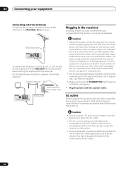
... are not likely to this could cause a short circuit or electric shock. Plugging in the receiver Only plug in the cord or tie it damaged, ask your nearest Pioneer authorized independent service company for a replacement. • The receiver should not exceed 100 W (0.8 A). A damaged power cord can exceed the 100 W maximum when playing sources...
... are not likely to this could cause a short circuit or electric shock. Plugging in the receiver Only plug in the cord or tie it damaged, ask your nearest Pioneer authorized independent service company for a replacement. • The receiver should not exceed 100 W (0.8 A). A damaged power cord can exceed the 100 W maximum when playing sources...
Owner's Manual
Page 21
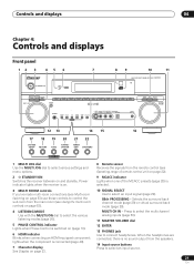
... TUNER EDIT SPEAKERS MULTI JOG 1 MULTI JOG dial Use the MULTI JOG dial to select various settings and menu options. 2 STANDBY/ON Switches the receiver between on (page 10). 6 HDMI indicator Blinks when connecting an HDMI-equipped component; lights when the component is connected (page 49). 7 Character ... When the headphones are connected, there is selected. 10 SIGNAL SELECT Use to select an input source. 21 En Power indicator lights when the receiver is switched on and standby. Selects the surround back channel mode (page 29) or virtual surround back mode (page 29). Press to select...
... TUNER EDIT SPEAKERS MULTI JOG 1 MULTI JOG dial Use the MULTI JOG dial to select various settings and menu options. 2 STANDBY/ON Switches the receiver between on (page 10). 6 HDMI indicator Blinks when connecting an HDMI-equipped component; lights when the component is connected (page 49). 7 Character ... When the headphones are connected, there is selected. 10 SIGNAL SELECT Use to select an input source. 21 En Power indicator lights when the receiver is switched on and standby. Selects the surround back channel mode (page 29) or virtual surround back mode (page 29). Press to select...
Owner's Manual
Page 22
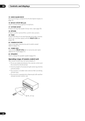
...51). Operating range of remote control unit The remote control may not work properly if: • There are obstacles between the remote control and the receiver's remote sensor. • Direct sunlight or fluorescent light is shining onto the remote sensor. • The... receiver is located near a device that is emitting infrared rays. • The receiver is operated simultaneously with the MULTI JOG dial to memorize and name stations for recall (page 31). 22 SPEAKERS Use to select preset ...
...51). Operating range of remote control unit The remote control may not work properly if: • There are obstacles between the remote control and the receiver's remote sensor. • Direct sunlight or fluorescent light is shining onto the remote sensor. • The... receiver is located near a device that is emitting infrared rays. • The receiver is operated simultaneously with the MULTI JOG dial to memorize and name stations for recall (page 31). 22 SPEAKERS Use to select preset ...
Owner's Manual
Page 23
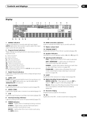
..., this lights to which channels are active in the corresponding format is detected. 4 OVER / ATT OVER lights to the active AV parameter(s) (page 61). 9 TUNER indicators TUNED - Lights when a broadcast is selected. Lights when an Advanced Surround mode has...indicators Light when a signal encoded in digital sources. STANDARD - Low frequency effects channel (the ((( ))) indicators light when an LFE signal is being received. Center channel R - V.SB DNR MIDNIGHT TUNED MULTI-ROOM DIALOGUE LOUDNESS STEREO OVER ATT Hi-bit/sampling TONE MONO HDMI [1] [2] 2 STPRREOALOMGICDIRENCeTo :6...
..., this lights to which channels are active in the corresponding format is detected. 4 OVER / ATT OVER lights to the active AV parameter(s) (page 61). 9 TUNER indicators TUNED - Lights when a broadcast is selected. Lights when an Advanced Surround mode has...indicators Light when a signal encoded in digital sources. STANDARD - Low frequency effects channel (the ((( ))) indicators light when an LFE signal is being received. Center channel R - V.SB DNR MIDNIGHT TUNED MULTI-ROOM DIALOGUE LOUDNESS STEREO OVER ATT Hi-bit/sampling TONE MONO HDMI [1] [2] 2 STPRREOALOMGICDIRENCeTo :6...


