Pioneer VSX 108 - AV Receiver Support and Manuals
Get Help and Manuals for this Pioneer item
View All Support Options Below
Free Pioneer VSX 108 manuals!
Problems with Pioneer VSX 108?
Ask a Question
Free Pioneer VSX 108 manuals!
Problems with Pioneer VSX 108?
Ask a Question
Most Recent Pioneer VSX 108 Questions

Vsx-819h Has A Humming Noise...
My Pioneer VSX-819H emits a humming noise thru the speakers when turned on.How can I resolve this?
My Pioneer VSX-819H emits a humming noise thru the speakers when turned on.How can I resolve this?
(Posted by CNAHM 2 years ago)

Sound Failure On Vsx-108.
The sound on the "TV" setting has failed. The other functions work (FM, AM, VCR). Is there a fuse or...
The sound on the "TV" setting has failed. The other functions work (FM, AM, VCR). Is there a fuse or...
(Posted by wjg4 6 years ago)

Reciever Won't Come On
when I turn on receiver it say DC Out how do I get it to work agai
when I turn on receiver it say DC Out how do I get it to work agai
(Posted by Anonymous-162052 7 years ago)


Led Indicator Has No Lights
It powers on and has lights every were else but the led indicator why?
It powers on and has lights every were else but the led indicator why?
(Posted by Youngtunechiab 8 years ago)
Popular Pioneer VSX 108 Manual Pages
Service Manual - Page 1
... GENERAL INFORMATION 26 7.1 PARTS 26 7.1.1 IC 26 7.1.2 DISPLAY 33
8. Type
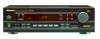
Model VSX-108
Power Requirement
Remarks
KUXCN
AC120V
CONTENTS
1. PCB PARTS LIST 22 6.
P.O. AUDIO MULTI - EXPLODED VIEWS AND PARTS LIST 3 3. PANEL FACILITIES AND SPECIFICATIONS ....... 35
PIONEER CORPORATION 4-1, Meguro 1-chome, Meguro-ku, Tokyo 153-8654, Japan
PIONEER ELECTRONICS SERVICE, INC.
Service Manual - Page 2

... the PIONEER recommended replacement one, shown in the parts list in this Service Manual, may void the warranty. Improperly performed repairs can be obtained by connecting a leakage current tester such as Simpson Model 229-2 or equivalent between the earth ground and all exposed metal surfaces
Also test with a on the schematics and on the parts list in this Service Manual. If...
Service Manual - Page 3
... LIST
Mark No. Therefore, when replacing, be sure to use parts of identical designation.
• Screws adjacent to mark on some component parts indicates the importance of the safety factor of the part. Bag (10 × 15) 10 Poly.
VSX-108
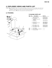
2. Description
1 AM Loop Antenna 2 FM Antenna 3 Operating Instructions
(English) 4 Polyform L
5 Polyform R 6 Remote Control Unit 7 Carton Box
8 Poly...
Service Manual - Page 6
...
12
DATA 12
REMOTE 3
13
DC/O
13
6
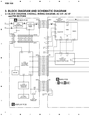
IC702 00202879-040 (BU2879AK) FL Driver IC
CN707
1
2
3
4
Q703, Q704
5
6
+5V
7
AC3.8V AC3.8V
-25V +5V GND SR GND
CN7
1 2 3 4 5 6 7
B MAIN PCB B 1/2, B 2/2
V1 FL TUBE 04991693-001
1
2
CONTROL OUT
IC703
06104421-000
D
IR Receiver
G DISPLAY PCB
6
1
2
3
4
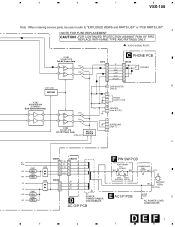
IND EO AM SIG. BLOCK DIAGRAM AND SCHEMATIC DIAGRAM
3.1 BLOCK DIAGRAM...
Service Manual - Page 7
5
6
7
8
VSX-108
Note : When ordering service parts, be sure to refer to "EXPLODED VIEWS and PARTS LIST" or "PCB PARTS LIST".
Q804 REG.
Q801 REG. D802 D803
CN207 1...
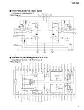
IC204 STK407-070 2ch AF Power Amp.
A
• NOTE FOR FUSE REPLACEMENT
CAUTION -FOR CONTINUED PROTECTION AGAINST RISK OF FIRE.
Q803 REG. Q209-Q211
RELAY DRIVER
SURROUND [Jack 7]
C
AC 3.8V
+5V +9V
+B -B -25V ...
Service Manual - Page 17
1
2
3
4
VSX-108
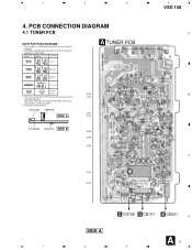
4. A comparison between the main parts of PCB diagrams.
IC101
Connector Capacitor
Q101
SIDE A
Q103
P.C.Board Chip Part SIDE B
Q105 Q106 IC102
C
Q107 Q104
CN708A
G CN708 G CN701 B CN201 D
SIDE A
A 17
1
2
3
4 View point of PCB and schematic diagrams is shown below. Part numbers in PCB diagrams match those in the schematic diagrams.
2. Symbol In PCB ...
Service Manual - Page 18
1
2
3
4
VSX-108
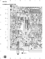
4.2 MAIN and PHONE PCBS
B MAIN PCB
A
Q212 Q213
Q209 Q211 IC208
Q203 Q204 IC203
IC204
B
Q205 Q206
IC201
Q201 Q202
IC205
C
IC202
Q208 Q207
Q402 Q401
Q801 Q804
D
B 18 1
J7 J5 J6
D
D CN207A
2
3
4
Service Manual - Page 27
Function
16
17 Host amp. VSX-108
• Pin Function
No. input/output
18
19
20 MPX output
21
22 MPX input
23 FM demodulation output
... C.F
11 FM S-meter output
12 AM S-meter output and AM SD sensitivity adjustment
13 AM/FM IF buffer output and output control SW (mute SW)
14 Phase comparator Low-pass filter (Switch the FM/AM)
15 Pilot detector Low-pass filter (Forced monoral)(VCO...
Service Manual - Page 29
...
1
Ch. 2 -Vcc
45
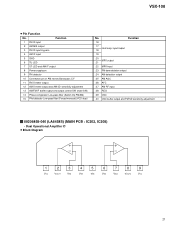
00262419-010 (M62419FP) (MAIN PCB : IC203)
• Digital Sound Controller with Tone Control IC
• Block Diagram
CLOCK VDD SELECT OUT2 VCL IN2 LOUD IN2 SELECT NF2 SELECT2 INA SELECT2 INB ...1 10
IN
TR3
Ch. 1 NF
11
R4 TR4
R5
TR8 D3
C.C.C. VSX-108
STK407-070 (MAIN PCB : IC204, IC205)
• 2-Channel AF Power Amplifier IC
• Block Diagram
Ch. 1 OUT
Pre.
Service Manual - Page 30
VSX-108
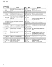
• Pin Function
No. Name
Function
1 DATA
Control data input Inputs a data by synchronizing with CLOCK.
2 GND
Ground
3 SELECT OUT1 Output pin of the input selector switch section
4 VOL IN1
Input pin of the volume section
5 LOUD IN1
Frequency characteristic setting pin of the input selector switch section
41 VDD
Digital power supply...
Service Manual - Page 31
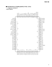
00272358-040 (LC72358N) (DISPLAY PCB : IC701)
• 1-Chip PLL Controller IC
• Block Diagram
VSX-108
XOUT TEST1 ED1 ED2 VSS FMIN AMIN VDD SUBPD ED3 HCTR LCTR SNS HOLD PH0/ADI0 PH1/ADI1
XIN TEST2 SI0/PG3 SO0/PG2 SCK0/...
Service Manual - Page 32
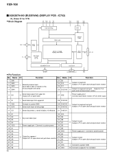
...bit Latch 16 bit × 15 word Display Data RAM
Control Logic
Grid
Driver
10
G10 - G1
32 - 37, 39 - 42
SEGMENT Driver
• Pin Function
No.
S16/G11
VEE
No. Name...-down resistor
I /O Connect a capacitor for oscillation VSX-108
00202879-040 (BU2879AK) (DISPLAY PCB : IC702)
• FL Driver IC for grid Output is P ch open -drain
S/G Driver
5
26, 28 - 31
38
S12/G15 -...
Service Manual - Page 35
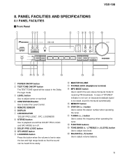
PANEL FACILITIES AND SPECIFICATIONS
8.1 PANEL FACILITIES
Front Panel
VSX-108
1 POWER ON/OFF button 2 TEST TONE ON...LEVEL button Use to adjust center or rear level 4 CENTER/REAR button Use to select the Level Control. 5 REMOTE SENSOR 6 DISPLAY 7 LED INDICATOR "DOLBY PRO LOGIC", SFC, LOUDNESS 8 STEREO button Use to ... R) button Use to switch the auto stereo/monaural mode for receiving FM broadcasts.
Service Manual - Page 38
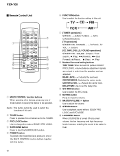
...] STANDBY/ON, 4, ¢ (Chapter / Track search), 2 (Play), 1 (Rewind), ¡ (Fast Forward), 8 (Pause), 7 (Stop), 3 (Play)
8 Number/Surround setting buttons...set the delay time.
9 SFC MODE button Use to switch the SFC mode.
0 MUTING button Press to mute the volume.
-
CENTER MODE: Switches the center mode. VSX-108
Remote Control Unit
7 1
8
2
3
9
4
0
5
~
-
6
=
1 MULTI CONTROL...
Service Manual - Page 39

... 210 W Dimensions 420 (W) x 123 (H) x 321 (D) mm Weight (without notice, due to possible modifications without package 6.0 kg
Furnished Parts FM Antenna 1 AM Loop Antenna 1 Dry Cell Batteries [size "AA" (IEC R6P 2 Remote Control Unit 1 RCA Cable 1 Operating Instructions 1
NOTE: Specifications and the design are trademarks of Dolby Laboratories Licensing Corporation.
39
Pioneer VSX 108 Reviews
We have not received any reviews for Pioneer yet.