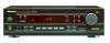
Pioneer VSX 108 Support Question
Pioneer VSX 108 Support Question
Find answers below for this question about Pioneer VSX 108 - AV Receiver.Need a Pioneer VSX 108 manual? We have 1 online manual for this item!
Question posted by Youngtunechiab on September 9th, 2015
Led Indicator Has No Lights
It powers on and has lights every were else but the led indicator why?
Current Answers
Answer #1: Posted by TechSupport101 on September 10th, 2015 12:03 AM
TechSupport101

Member since:
May 24th, 2013 Points: 12,171,285

Member since:
May 24th, 2013 Points: 12,171,285
Well LEDs are not prone to fail unless there is serious power surge. This means that you may have a failed dependency. See the model's service manual here http://elektrotanya.com/pioneer_vsx-108.pdf/download.html
Related Pioneer VSX 108 Manual Pages
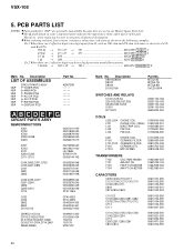
Service Manual - Page 1
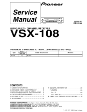
...Long Beach, CA 90801-1760, U.S.A. Haven 1087, Keetberglaan 1, 9120 Melsele, Belgium PIONEER ELECTRONICS ASIACENTRE PTE. BLOCK DIAGRAM AND SCHEMATIC DIAGRAM ..... 6 4. P.O.
ADJUSTMENT 24
7. AUDIO MULTI - CHANNEL RECEIVER
VSX-108
ORDER NO.
Type
Model VSX-108
Power Requirement
Remarks
KUXCN
AC120V
CONTENTS
1. PIONEER ELECTRONIC (EUROPE) N.V. IZE OCT. 1999 Printed in Japan
Service Manual - Page 2

... a 120V AC 60Hz outlet and turn the AC power switch on.
Replacement parts which does not have been trained to a qualified service technician. VSX-108
1.
Proposition 65
NOTICE
(FOR CANADIAN MODEL ONLY)
... ground and all exposed metal surfaces
Also test with a on the schematics and on PCB indicate that replacement parts must not exceed 0.5mA. If you should not risk trying to do...
Service Manual - Page 3
... to mark on the product are not in our Master Spare Parts List. • The mark found on some component parts indicates the importance of the safety factor of the part. VSX-108
2.
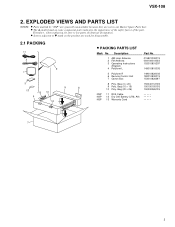
Bag (10 × 15) 10 Poly. EXPLODED VIEWS AND PARTS LIST
• NOTES: Parts marked by "NSP" are generally unavailable...
Service Manual - Page 5
... Lens
AZW7259
13000000001S 11701080101S
11 Volume Knob 12 Front Panel 13 Front Cabinet 14 Power Button 15 Function Button
12701081010S 10801080010S 10101080001AS 12801080001S 12801082001S
16 17 Mounting Bracket A ...26 Screw
BBZ30P100FZK
27 Screw
FBT40P080FZK
28 Screw
14453016202S
29 Power transformar (AC120V) 01801088522S
30 AC Power Cord
02360040009S
NSP NSP NSP
31 Fuse (F801 : ...
Service Manual - Page 6
... +5V GND SR GND
CN7
1 2 3 4 5 6 7
B MAIN PCB B 1/2, B 2/2
V1 FL TUBE 04991693-001
1
2
CONTROL OUT
IC703
06104421-000
D
IR Receiver
G DISPLAY PCB
6
1
2
3
4 AM SD ST. IND EO AM SIG. FM IF REQ. MONO
- 1
2
3
4
VSX-108
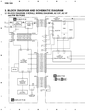
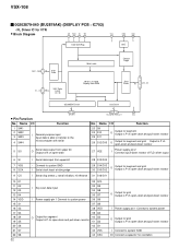
3. BLOCK DIAGRAM AND SCHEMATIC DIAGRAM
3.1 BLOCK DIAGRAM, OVERALL WIRING DIAGRAM, AC O/P, AC I/P
A
and PW SW PCBS
FM ANTENNA
AM...
Service Manual - Page 7
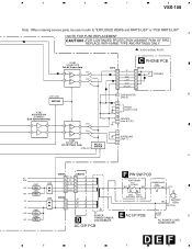
... 01801088522S
AC O/P PCB
E AC I/P PCB
R820
3M3
D
AC POWER CORD 02360040009S
DEF 7
5
6
7
8 Q209-Q211
RELAY DRIVER
SURROUND [Jack 7]
C
AC 3.8V
+5V +9V
+B -B -25V -9V
Q802 REG.
A
• NOTE FOR FUSE REPLACEMENT
CAUTION -FOR CONTINUED PROTECTION AGAINST RISK OF FIRE. 5
6
7
8
VSX-108
Note : When ordering service parts, be sure to refer to "EXPLODED VIEWS...
Service Manual - Page 10
1
2
VSX-108
3.3 MAIN PCB (1/2)
A JACK4
JACK3
JACK2 IN
B
3
4
B 1/2 MAIN PCB
A CN102
CN201
T
IC203 00262419-010
(M62419)
VCR
T
OUT JACK1
C
05208000-000
IC201
00201041-040
S
(LV1041M)
C
D
10 B 1/2
1
2
3
4
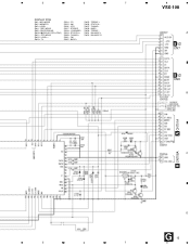
Service Manual - Page 11
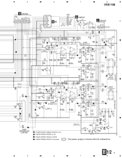
5
G CN702
CN6
6
B 2/2
7
8
VSX-108
CN7
G CN707
Q213 00310536-046
C CN14A
A
Q212
00310536-046
R L GND L-SP R-ST SP-OFF
CN14
S
S C
C
Q203 00302576-040
Q204 ... AUDIO SIGNAL ROUTE (L ch)
D209 00494001-300
Q211
Q209
: AUDIO SIGNAL ROUTE (L ch)
C
: AUDIO SIGNAL ROUTE (Center)
D
S
: AUDIO SIGNAL ROUTE (Surround)
: The power supply is shown with the marked box. B 1/2 11
5
6
7
8
Service Manual - Page 12
B
B 1/2
C
D
12 B 2/2
1
2
3
4 1
2
3
4
VSX-108
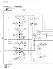
3.4 MAIN (2/2) and PHONE PCBS
A
B 2/2 MAIN PCB
: The power supply is shown with the marked box.
Service Manual - Page 15
... : STEREO SW18 : LOUDNESS SW19 : STATION + SW20 : TUNING + SW21 : FM SW22 : BASS +
SW23 : TREBLE + SW26 : STATION SW27 : TUNING SW29 : BASS SW30 : TREBLE SW31 : BALANCE L SW32 : BALANCE R
8
VSX-108
A
B 1/2
CN7
B 1/2
CN6
B
A CN701A
A CN708A
C
D
G 15
5
6
7
8
Service Manual - Page 17
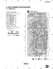
Part numbers in PCB diagrams match those in the schematic diagrams.
2. 1
2
3
4
VSX-108
4. Symbol In PCB Diagrams
Symbol In Schematic Diagrams B C EB C E
Part Name
BCE
Transistor
BCE
B C EB C E
Transistor with the schematic diagram.
4. The parts mounted on this ...
Service Manual - Page 18
1
2
3
4
VSX-108
4.2 MAIN and PHONE PCBS
B MAIN PCB
A
Q212 Q213
Q209 Q211 IC208
Q203 Q204 IC203
IC204
B
Q205 Q206
IC201
Q201 Q202
IC205
C
IC202
Q208 Q207
Q402 Q401
Q801 Q804
D
B 18 1
J7 J5 J6
D
D CN207A
2
3
4
Service Manual - Page 21

Q711-Q713
Q714
IC701
Q702 Q701
5
6
7
C
A
CN708A
A
CN701A D
G 21
8
5
6
7
8
VSX-108
A
08 07
B
B CN7 B CN6
AC1.9V AC1.9V -25V +5V GND SR OUT GND J718 DATA CLK E1 DATA CLK E2 DGND MUTE OVER SP-...
Service Manual - Page 22
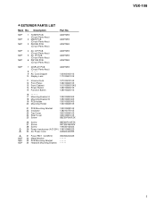
... When there are not in our Master Spare Parts List. •The mark found on some component parts indicates the importance of the safety factor of identical designation.
•When ordering resistors, first convert resistance values into... F101,F102 F104 F1010
CHOKE COIL CERAMIC FILTER CERAMIC FILTER CERAMIC DTS. VSX-108
Mark No.
BPF GFWB3
01710205-100 02800450-000 02810700-009 02810700-025...
Service Manual - Page 23
... CEAT101M35 CEAT101M35
CEAT102M10 CEAT1R0M50 CEAT220M50 CEAT221M10 CEAT222M25
CEAT2R2M50 CEAT330M16 CEAT3R3M50 CEAT470M10 CEAT470M10
CEAT470M25 CEAT470M35 CEAT471M10 CEAT4R7M50 CEAT4R7M50
CEAT4R7M50 CEAT4R7M50 CEAT4R7M50 CEATR33M50 CEATR47M50
CEATR47M50 01410200-003
VSX-108
Mark No.
Service Manual - Page 25
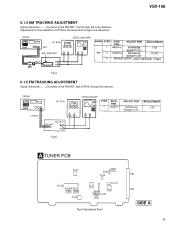
VSX-108
Fig.4
6.1.5 FM TRACKING ADJUSTMENT
Signal Generator.........Connects to the FM ANT Jack (FM IN) through the Loop Antenna. Fig.5
A... 3
T101
TP2 IC101
L102
Fig.6 Adjustment Point
FM AM
SIDE A
25 Coil through the dummy.
Adjustment for the indication of VTVM of the wave form scope to the AM ANT. 6.1.4 AM TRACKING ADJUSTMENT
Signal Generator.........Connects to be maximum.
Service Manual - Page 27
...input
2 AM MIX output
3 FM IF input by-pass
4 AM IF input
5 GND
6 TU-LED
7 ST-LED and AM IF output
8 Power supply pin
9 FM detector
10 Connection pin of AM narrow Band-pass C.F
11 FM S-meter output... Amplifier IC
• Block Diagram
1
2
3
4
5
6
7
8
9
VCC
VOUT1
VIN1
VIN1
VEE
VIN2
VIN2
VOUT2
VCC
27
VSX-108
• Pin Function
No. Function
16
17 Host amp.
Service Manual - Page 32
...43 VSS
44 OSC
O
Output for grid Output is P ch open-drain and pull-down resistor
I Power supply pin 1 Connect to system power
O Output for grid Output is P ch open-drain and pull-down resistor
I Connect to the
...
SEGMENT Driver
• Pin Function
No. OSC
VDD
44
38
OSC
1-4
SW1 - VSX-108
00202879-040 (BU2879AK) (DISPLAY PCB : IC702)
• FL Driver IC for oscillation
Service Manual - Page 35
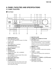
... mode for receiving FM broadcasts. PANEL FACILITIES AND SPECIFICATIONS
8.1 PANEL FACILITIES
Front Panel
VSX-108
1 POWER ON/OFF ...button 2 TEST TONE ON/OFF button
The TEST TONE signal will be output in the Dolby Pro logic mode. 3 LEVEL button Use to adjust center or rear level 4 CENTER/REAR button Use to select the Level Control. 5 REMOTE SENSOR 6 DISPLAY 7 LED INDICATOR...
Service Manual - Page 37
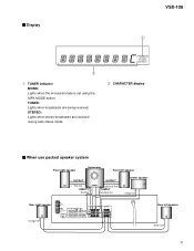
... speaker
Rear left speaker
- Green line
37 TUNED: Lights when broadcasts are received during auto stereo mode.
2 CHARACTER display
When use packed speaker system
Front right speaker
Subwoofer
Front left speaker
+- Display
VSX-108
SP A DIRECT LOUDNESS PRO LOGIC VIRTUAL DSP TAPE 2
MONO TUNED STEREO
1 TUNER indicator MONO: Lights when the monaural mode is set using the...
Similar Questions

I Cant Connect To The Bluetooth
i am not able to connect any device via Bluetooth to my pioneer Htz-bd 32
i am not able to connect any device via Bluetooth to my pioneer Htz-bd 32
(Posted by kemekalgh 2 years ago)

I Am Looking For Slovak Or Czech Manual For Pioneer Vsx- 819h - K - Av Receiver
I am looking for Slovak or Czech manual for Pioneer VSX- 819H - K - AV Receiver
I am looking for Slovak or Czech manual for Pioneer VSX- 819H - K - AV Receiver
(Posted by lubourban 8 years ago)

Green Indicator Lights.
How do I manage to get woofer and main unit to display green lights.
How do I manage to get woofer and main unit to display green lights.
(Posted by mmurray6 11 years ago)
Operating
tring to hook up system but there are tow light on it and it wont come on
tring to hook up system but there are tow light on it and it wont come on
(Posted by rheard49 12 years ago)

Pioneer Htp-2920 Home Theater SystemConnect To Cable Box Or Tv?
I hooked up htp2920 as instructed. I hooke the cables from the pioneer system directly to tv., not...
I hooked up htp2920 as instructed. I hooke the cables from the pioneer system directly to tv., not...
(Posted by mmorris3 13 years ago)