Service Manual
Page 1
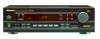
.... CHANNEL RECEIVER VSX-108 ORDER NO. PCB PARTS LIST 22 6. IZE OCT. 1999 Printed in Japan Type Model VSX-108 Power Requirement Remarks KUXCN AC120V CONTENTS 1. PIONEER ELECTRONIC (EUROPE) N.V. GENERAL INFORMATION 26 7.1 PARTS 26 7.1.1 IC 26 7.1.2 DISPLAY 33 8. Box 1760, Long Beach, CA 90801-1760, U.S.A. SAFETY INFORMATION 2 2. PANEL FACILITIES AND SPECIFICATIONS ....... 35 PIONEER CORPORATION 4-1, Meguro 1-chome, Meguro-ku, Tokyo 153-8654, Japan PIONEER ELECTRONICS SERVICE, INC. PCB CONNECTION DIAGRAM 17 5. AUDIO MULTI...
.... CHANNEL RECEIVER VSX-108 ORDER NO. PCB PARTS LIST 22 6. IZE OCT. 1999 Printed in Japan Type Model VSX-108 Power Requirement Remarks KUXCN AC120V CONTENTS 1. PIONEER ELECTRONIC (EUROPE) N.V. GENERAL INFORMATION 26 7.1 PARTS 26 7.1.1 IC 26 7.1.2 DISPLAY 33 8. Box 1760, Long Beach, CA 90801-1760, U.S.A. SAFETY INFORMATION 2 2. PANEL FACILITIES AND SPECIFICATIONS ....... 35 PIONEER CORPORATION 4-1, Meguro 1-chome, Meguro-ku, Tokyo 153-8654, Japan PIONEER ELECTRONICS SERVICE, INC. PCB CONNECTION DIAGRAM 17 5. AUDIO MULTI...

Service Manual
Page 2
... test with a on the schematics and on the parts list in this Service Manual. The use of a substitute replacement component which does not have special safety related characteristics. AC Leakage Test 2 Plug the AC line cord of identical designation. (slow operating fuse) on . Replacement parts which are known to time. SAFETY INFORMATION This service manual is continuously under test Reading should Leakage current not be of the appliance directly...
... test with a on the schematics and on the parts list in this Service Manual. The use of a substitute replacement component which does not have special safety related characteristics. AC Leakage Test 2 Plug the AC line cord of identical designation. (slow operating fuse) on . Replacement parts which are known to time. SAFETY INFORMATION This service manual is continuously under test Reading should Leakage current not be of the appliance directly...
Service Manual
Page 3
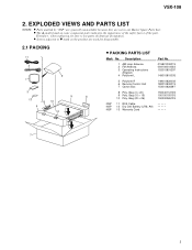
VSX-108 2. Bag (10 × 15) 10 Poly. Bag (20 × 26) NSP NSP NSP 11 RCA Cable 12 Dry Cell Battery (LR6, AA) 13 Warranty Card Part No. 01582100001S 06410001003S 152010801297 14901081000S 14901082000S 18201080001S 153010820297 15004011210S 15010015510S 15020026510S 7 3 Bag (4 × 20) 9 Poly. Description 1 AM Loop Antenna 2 FM Antenna 3 Operating Instructions (English) 4 Polyform L 5 Polyform R 6 Remote Control Unit 7 Carton Box 8 Poly. EXPLODED VIEWS AND...
VSX-108 2. Bag (10 × 15) 10 Poly. Bag (20 × 26) NSP NSP NSP 11 RCA Cable 12 Dry Cell Battery (LR6, AA) 13 Warranty Card Part No. 01582100001S 06410001003S 152010801297 14901081000S 14901082000S 18201080001S 153010820297 15004011210S 15010015510S 15020026510S 7 3 Bag (4 × 20) 9 Poly. Description 1 AM Loop Antenna 2 FM Antenna 3 Operating Instructions (English) 4 Polyform L 5 Polyform R 6 Remote Control Unit 7 Carton Box 8 Poly. EXPLODED VIEWS AND...
Service Manual
Page 5
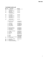
... Parts Assy) 8 9 AC Cord Stopper 10 Display Lens AZW7259 13000000001S 11701080101S 11 Volume Knob 12 Front Panel 13 Front Cabinet 14 Power Button 15 Function Button 12701081010S 10801080010S 10101080001AS 12801080001S 12801082001S 16 17 Mounting Bracket A 18 Mounting Bracket B 19 PCB Holder 20 Mounting Holder 12901089000S 12901089100S 13001082000S 13301082310S 21 PCB Mounting Bracket 22 Insullator 23 Top Cover 24 Rear Cover...
... Parts Assy) 8 9 AC Cord Stopper 10 Display Lens AZW7259 13000000001S 11701080101S 11 Volume Knob 12 Front Panel 13 Front Cabinet 14 Power Button 15 Function Button 12701081010S 10801080010S 10101080001AS 12801080001S 12801082001S 16 17 Mounting Bracket A 18 Mounting Bracket B 19 PCB Holder 20 Mounting Holder 12901089000S 12901089100S 13001082000S 13301082310S 21 PCB Mounting Bracket 22 Insullator 23 Top Cover 24 Rear Cover...
Service Manual
Page 6
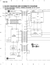
.... BLOCK DIAGRAM AND SCHEMATIC DIAGRAM 3.1 BLOCK DIAGRAM, OVERALL WIRING DIAGRAM, AC O/P, AC I/P A and PW SW PCBS FM ANTENNA AM ANTENNA A TUNER PCB CN102 1 FM 1 IC101 FM 9 1 IC102 TUNER 2 LA1186N 00201838-040 16 3 FM FRONT END (LA1838) ELECTRIC 17 4 AM 8 TUNING 5 27 30 Q102 CN708A 12 CN701A 1 2 3 4 5 6 7 8 9 10 TUNER-R GND TUNER-L +5V +9V CN201 1 IC203 00262419-010 (M62419) Digital Sound Controller 2 TUNER 3 36 L 4 7R 26 17 LR TONE OUT...
.... BLOCK DIAGRAM AND SCHEMATIC DIAGRAM 3.1 BLOCK DIAGRAM, OVERALL WIRING DIAGRAM, AC O/P, AC I/P A and PW SW PCBS FM ANTENNA AM ANTENNA A TUNER PCB CN102 1 FM 1 IC101 FM 9 1 IC102 TUNER 2 LA1186N 00201838-040 16 3 FM FRONT END (LA1838) ELECTRIC 17 4 AM 8 TUNING 5 27 30 Q102 CN708A 12 CN701A 1 2 3 4 5 6 7 8 9 10 TUNER-R GND TUNER-L +5V +9V CN201 1 IC203 00262419-010 (M62419) Digital Sound Controller 2 TUNER 3 36 L 4 7R 26 17 LR TONE OUT...
Service Manual
Page 7
... DRIVER SURROUND [Jack 7] C AC 3.8V +5V +9V +B -B -25V -9V Q802 REG. 5 6 7 8 VSX-108 Note : When ordering service parts, be sure to refer to "EXPLODED VIEWS and PARTS LIST" or "PCB PARTS LIST". REPLACE WITH SAME TYPE AND RATINGS ONLY. : AUDIO SIGNAL ROUTE IC204 STK407-070 2ch AF Power Amp. RY1 10 6 RY2 14 7 CN14 1 2 3 4 5 6 R L GND L-SP R-ST SP-OFF C PHONE PCB CN14A 1 2 3 4 5 6 PHONES Q201-Q204 SUB WOOFER B [Jack...
... DRIVER SURROUND [Jack 7] C AC 3.8V +5V +9V +B -B -25V -9V Q802 REG. 5 6 7 8 VSX-108 Note : When ordering service parts, be sure to refer to "EXPLODED VIEWS and PARTS LIST" or "PCB PARTS LIST". REPLACE WITH SAME TYPE AND RATINGS ONLY. : AUDIO SIGNAL ROUTE IC204 STK407-070 2ch AF Power Amp. RY1 10 6 RY2 14 7 CN14 1 2 3 4 5 6 R L GND L-SP R-ST SP-OFF C PHONE PCB CN14A 1 2 3 4 5 6 PHONES Q201-Q204 SUB WOOFER B [Jack...
Service Manual
Page 11
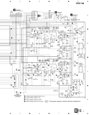
...-040 L203 01500030-006 C Q207 C L204 S 01500030-006 S Q208 C CENTER B JACK6 04610400-006 C JACK7 04620800-001 C S FRONT D211 00494001-300 D212 00494001-300 SURROUND Q205-Q211 : 00310536-046 Q210 C IC202 00206458-040 (LA6458S) T : TUNER AUDIO SIGNAL ROUTE (L ch) D209 00494001-300 Q211 Q209 : AUDIO SIGNAL ROUTE (L ch) C : AUDIO SIGNAL ROUTE (Center) D S : AUDIO SIGNAL ROUTE (Surround) : The power supply is shown with the marked box. B 1/2 11 5 6 7 8
...-040 L203 01500030-006 C Q207 C L204 S 01500030-006 S Q208 C CENTER B JACK6 04610400-006 C JACK7 04620800-001 C S FRONT D211 00494001-300 D212 00494001-300 SURROUND Q205-Q211 : 00310536-046 Q210 C IC202 00206458-040 (LA6458S) T : TUNER AUDIO SIGNAL ROUTE (L ch) D209 00494001-300 Q211 Q209 : AUDIO SIGNAL ROUTE (L ch) C : AUDIO SIGNAL ROUTE (Center) D S : AUDIO SIGNAL ROUTE (Surround) : The power supply is shown with the marked box. B 1/2 11 5 6 7 8
Service Manual
Page 15
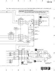
5 6 7 DISPLAY PCB SW1 : MPX MODE SW2 : MEMORY SW3 : LEVEL SW4 : TEST MODE SW5 : CENTER/REAR SW10 : (DOLBY PRO LOGIC) SW11 : SFC MODE SW12 : LEVEL + SW13 : TV SW14 : CD SW15 : AM SW16 : VCR SW17 : STEREO SW18 : LOUDNESS SW19 : STATION + SW20 : TUNING + SW21 : FM SW22 : BASS + SW23 : TREBLE + SW26 : STATION SW27 : TUNING SW29 : BASS SW30 : TREBLE SW31 : BALANCE L SW32 : BALANCE R 8 VSX-108 A B 1/2 CN7 B 1/2 CN6 B A CN701A A CN708A C D G 15 5 6 7 8
5 6 7 DISPLAY PCB SW1 : MPX MODE SW2 : MEMORY SW3 : LEVEL SW4 : TEST MODE SW5 : CENTER/REAR SW10 : (DOLBY PRO LOGIC) SW11 : SFC MODE SW12 : LEVEL + SW13 : TV SW14 : CD SW15 : AM SW16 : VCR SW17 : STEREO SW18 : LOUDNESS SW19 : STATION + SW20 : TUNING + SW21 : FM SW22 : BASS + SW23 : TREBLE + SW26 : STATION SW27 : TUNING SW29 : BASS SW30 : TREBLE SW31 : BALANCE L SW32 : BALANCE R 8 VSX-108 A B 1/2 CN7 B 1/2 CN6 B A CN701A A CN708A C D G 15 5 6 7 8
Service Manual
Page 17
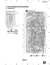
... further information for several destinations. 1 2 3 4 VSX-108 4. Part numbers in PCB diagrams match those in the schematic diagrams. 2. View point of PCB and schematic diagrams is shown below. Symbol In PCB Diagrams Symbol In Schematic Diagrams B C EB C E Part Name BCE Transistor BCE B C EB C E Transistor with the schematic diagram. 4. PCB CONNECTION DIAGRAM 4.1 TUNER PCB A NOTE FOR PCB DIAGRAMS : 1. The parts mounted on this PCB include all necessary parts for respective destinations, be sure...
... further information for several destinations. 1 2 3 4 VSX-108 4. Part numbers in PCB diagrams match those in the schematic diagrams. 2. View point of PCB and schematic diagrams is shown below. Symbol In PCB Diagrams Symbol In Schematic Diagrams B C EB C E Part Name BCE Transistor BCE B C EB C E Transistor with the schematic diagram. 4. PCB CONNECTION DIAGRAM 4.1 TUNER PCB A NOTE FOR PCB DIAGRAMS : 1. The parts mounted on this PCB include all necessary parts for respective destinations, be sure...
Service Manual
Page 22
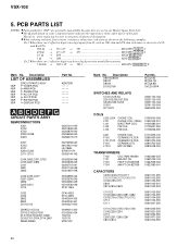
...-550 00610471-250 00610472-550 22 Description Part No. 5. Therefore, when replacing, be sure to use parts of the part. Ex.1 When there are 2 effective digits (any digit apart from 0), such as 560 ohm and...Master Spare Parts List. •The mark found on some component parts indicates the importance of the safety factor of identical designation. •When ordering resistors, first convert resistance values into code form as in the following examples. VSX-108 Mark No. Description Part No. Description LIST OF ASSEMBLIES NSP NSP NSP NSP NSP NSP NSP CIRCUIT PARTS ASSY TUNER...
...-550 00610471-250 00610472-550 22 Description Part No. 5. Therefore, when replacing, be sure to use parts of the part. Ex.1 When there are 2 effective digits (any digit apart from 0), such as 560 ohm and...Master Spare Parts List. •The mark found on some component parts indicates the importance of the safety factor of identical designation. •When ordering resistors, first convert resistance values into code form as in the following examples. VSX-108 Mark No. Description Part No. Description LIST OF ASSEMBLIES NSP NSP NSP NSP NSP NSP NSP CIRCUIT PARTS ASSY TUNER...
Service Manual
Page 24
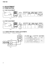
ADJUSTMENT 6.1 TUNER SECTION 6.1.1 AM IF ADJUSTMENT Fig.1 6.1.2 FM IF ADJUSTMENT Fig.2 6.1.3 TUNING FREQUENCY RANGE ADJUSTMENTS (FM, AM) DC Voltmeter.........Connect to TP1 and GND Fig.3 24 VSX-108 6.
ADJUSTMENT 6.1 TUNER SECTION 6.1.1 AM IF ADJUSTMENT Fig.1 6.1.2 FM IF ADJUSTMENT Fig.2 6.1.3 TUNING FREQUENCY RANGE ADJUSTMENTS (FM, AM) DC Voltmeter.........Connect to TP1 and GND Fig.3 24 VSX-108 6.
Service Manual
Page 25
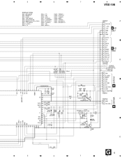
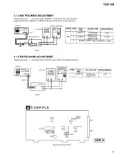
6.1.4 AM TRACKING ADJUSTMENT Signal Generator.........Connects to be maximum. Fig.5 A TUNER PCB T104 IC102 Pin 23 TP3 Pin 24 TP4 T102 TP1 R101 L104 TC101 T103 Pin 3 T101 TP2 IC101 L102 Fig.6 Adjustment Point FM AM SIDE A 25 Adjustment for the indication of VTVM of the wave form scope to the AM ANT. Coil through the dummy. VSX-108 Fig.4 6.1.5 FM TRACKING ADJUSTMENT Signal Generator.........Connects to the FM ANT Jack (FM IN) through the Loop Antenna.
6.1.4 AM TRACKING ADJUSTMENT Signal Generator.........Connects to be maximum. Fig.5 A TUNER PCB T104 IC102 Pin 23 TP3 Pin 24 TP4 T102 TP1 R101 L104 TC101 T103 Pin 3 T101 TP2 IC101 L102 Fig.6 Adjustment Point FM AM SIDE A 25 Adjustment for the indication of VTVM of the wave form scope to the AM ANT. Coil through the dummy. VSX-108 Fig.4 6.1.5 FM TRACKING ADJUSTMENT Signal Generator.........Connects to the FM ANT Jack (FM IN) through the Loop Antenna.
Service Manual
Page 26
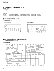
.... VSX-108 7. GENERAL INFORMATION 7.1 PARTS 7.1.1 IC • The information shown in the list is basic information and may not correspond exactly to that shown in the schematic diagrams. •List of IC LA1186N, STK407-070, 00201838-040 (LA1838), 00206458-040 (LA6458S), 00201041-040 (LV1041M), 00262419-010 (M62419FP), 00272358-040 (LC72358N), 00202879-040 (BU2879AK) LA1186N (TUNER PCB...
.... VSX-108 7. GENERAL INFORMATION 7.1 PARTS 7.1.1 IC • The information shown in the list is basic information and may not correspond exactly to that shown in the schematic diagrams. •List of IC LA1186N, STK407-070, 00201838-040 (LA1838), 00206458-040 (LA6458S), 00201041-040 (LV1041M), 00262419-010 (M62419FP), 00272358-040 (LC72358N), 00202879-040 (BU2879AK) LA1186N (TUNER PCB...
Service Manual
Page 27
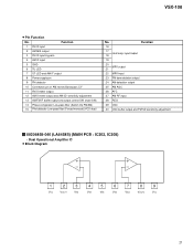
... output and FM SD sensitivity adjustment 00206458-040 (LA6458S) (MAIN PCB : IC202, IC208) • Dual Operational Amplifier IC • Block Diagram 1 2 3 4 5 6 7 8 9 VCC VOUT1 VIN1 VIN1 VEE VIN2 VIN2 VOUT2 VCC 27 Function 16 17 Host amp. VSX-108 • Pin Function No. Function 1 FM IF input 2 AM MIX output 3 FM IF input by-pass 4 AM IF input 5 GND 6 TU-LED 7 ST-LED and AM IF output 8 Power...
... output and FM SD sensitivity adjustment 00206458-040 (LA6458S) (MAIN PCB : IC202, IC208) • Dual Operational Amplifier IC • Block Diagram 1 2 3 4 5 6 7 8 9 VCC VOUT1 VIN1 VIN1 VEE VIN2 VIN2 VOUT2 VCC 27 Function 16 17 Host amp. VSX-108 • Pin Function No. Function 1 FM IF input 2 AM MIX output 3 FM IF input by-pass 4 AM IF input 5 GND 6 TU-LED 7 ST-LED and AM IF output 8 Power...
Service Manual
Page 30
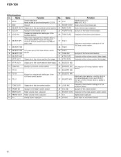
VSX-108 • Pin Function No. Name Function 1 DATA Control data input Inputs a data by synchronizing with CLOCK. 2 GND Ground 3 SELECT OUT1 Output pin of the input selector switch section 4 VOL IN1 Input pin of the volume section 5 LOUD IN1 Frequency characteristic setting pin of the loudness section 6 SELECT NF1 Adjust each input gain by a resistor which is connected between this pin and SELECT OUT pin, and the resistor which is...
VSX-108 • Pin Function No. Name Function 1 DATA Control data input Inputs a data by synchronizing with CLOCK. 2 GND Ground 3 SELECT OUT1 Output pin of the input selector switch section 4 VOL IN1 Input pin of the volume section 5 LOUD IN1 Frequency characteristic setting pin of the loudness section 6 SELECT NF1 Adjust each input gain by a resistor which is connected between this pin and SELECT OUT pin, and the resistor which is...
Service Manual
Page 32
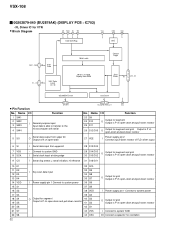
... resistor I Power supply pin 1 Connect to system power O Output for grid Output is N ch open -drain and pull-down resistor I /O Connect a capacitor for oscillation VSX-108 00202879-040 (BU2879AK) (DISPLAY PCB : IC702) • FL Driver IC for grid Output is P ch open -drain S/G Driver 5 26, 28 - 31 38 S12/G15 - Name I/O 11 15 - 25 S1 -S11 Function 1 SW1 2 SW2 3 SW3 4 SW4 I General-purpose input Input data is...
... resistor I Power supply pin 1 Connect to system power O Output for grid Output is N ch open -drain and pull-down resistor I /O Connect a capacitor for oscillation VSX-108 00202879-040 (BU2879AK) (DISPLAY PCB : IC702) • FL Driver IC for grid Output is P ch open -drain S/G Driver 5 26, 28 - 31 38 S12/G15 - Name I/O 11 15 - 25 S1 -S11 Function 1 SW1 2 SW2 3 SW3 4 SW4 I General-purpose input Input data is...
Service Manual
Page 35
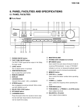
...In case of "STEREO" indicator is not turn on because broadcast signal is too weak, sound is low to adjust volume balance. 35 8. PANEL FACILITIES AND SPECIFICATIONS 8.1 PANEL FACILITIES Front Panel VSX-108 1 POWER ON/OFF button 2 TEST TONE ON/OFF button The TEST TONE signal will be output in the Dolby Pro logic mode. 3 LEVEL button Use to adjust center or rear level 4 CENTER/REAR button Use to select the Level Control. 5 REMOTE SENSOR 6 DISPLAY 7 LED INDICATOR "DOLBY PRO LOGIC", SFC, LOUDNESS 8 STEREO button Use to switch the auto stereo/monaural mode for receiving FM broadcasts.
...In case of "STEREO" indicator is not turn on because broadcast signal is too weak, sound is low to adjust volume balance. 35 8. PANEL FACILITIES AND SPECIFICATIONS 8.1 PANEL FACILITIES Front Panel VSX-108 1 POWER ON/OFF button 2 TEST TONE ON/OFF button The TEST TONE signal will be output in the Dolby Pro logic mode. 3 LEVEL button Use to adjust center or rear level 4 CENTER/REAR button Use to select the Level Control. 5 REMOTE SENSOR 6 DISPLAY 7 LED INDICATOR "DOLBY PRO LOGIC", SFC, LOUDNESS 8 STEREO button Use to switch the auto stereo/monaural mode for receiving FM broadcasts.
Service Manual
Page 37
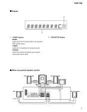
... line Rear right speaker Rear left speaker - OUTPUT OUTPUT - + Pink line Light blue line+ INPUT + - - + INPUT Red line Dark blue line Center speaker +- Orange line +- STEREO: Lights when stereo broadcasts are being received. Green line 37 Display VSX-108 SP A DIRECT LOUDNESS PRO LOGIC VIRTUAL DSP TAPE 2 MONO TUNED STEREO 1 TUNER indicator MONO: Lights when the monaural mode is set using the MPX MODE button. TUNED: Lights when broadcasts are received during auto stereo mode. 2 CHARACTER display When use packed speaker system Front right speaker Subwoofer Front...
... line Rear right speaker Rear left speaker - OUTPUT OUTPUT - + Pink line Light blue line+ INPUT + - - + INPUT Red line Dark blue line Center speaker +- Orange line +- STEREO: Lights when stereo broadcasts are being received. Green line 37 Display VSX-108 SP A DIRECT LOUDNESS PRO LOGIC VIRTUAL DSP TAPE 2 MONO TUNED STEREO 1 TUNER indicator MONO: Lights when the monaural mode is set using the MPX MODE button. TUNED: Lights when broadcasts are received during auto stereo mode. 2 CHARACTER display When use packed speaker system Front right speaker Subwoofer Front...
Service Manual
Page 38
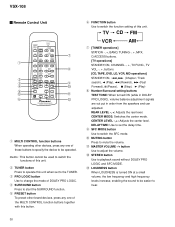
.... -, +, buttons [CD, TAPE, DVD, LD, VCR, MD operations] STANDBY/ON, 4, ¢ (Chapter / Track search), 2 (Play), 1 (Rewind), ¡ (Fast Forward), 8 (Pause), 7 (Stop), 3 (Play) 8 Number/Surround setting buttons TEST TONE: When turned ON (while in DOLBY PRO LOGIC), volume balance adjustment signals are out put in order from the speakers and can adjusted. REAR LEVEL -, +: Adjusts the rear level. DELAY TIME: Use to set to the TUNER. 3 PRO LOGIC button Use to change the mode of DOLBY PRO LOGIC. 4 SURROUND button Press to start the SURROUND function. 5 PRESET button To preset other...
.... -, +, buttons [CD, TAPE, DVD, LD, VCR, MD operations] STANDBY/ON, 4, ¢ (Chapter / Track search), 2 (Play), 1 (Rewind), ¡ (Fast Forward), 8 (Pause), 7 (Stop), 3 (Play) 8 Number/Surround setting buttons TEST TONE: When turned ON (while in DOLBY PRO LOGIC), volume balance adjustment signals are out put in order from the speakers and can adjusted. REAR LEVEL -, +: Adjusts the rear level. DELAY TIME: Use to set to the TUNER. 3 PRO LOGIC button Use to change the mode of DOLBY PRO LOGIC. 4 SURROUND button Press to start the SURROUND function. 5 PRESET button To preset other...

Service Manual
Page 39
... package 6.0 kg Furnished Parts FM Antenna 1 AM Loop Antenna 1 Dry Cell Batteries [size "AA" (IEC R6P 2 Remote Control Unit 1 RCA Cable 1 Operating Instructions 1 NOTE: Specifications and the design are trademarks of Dolby Laboratories Licensing Corporation. 39 VSX-108 8.2 SPECIFICATIONS Continous Power Output Front 50 W + 50 W (1kHz, 0.9%, 8 Ω) Center 50 W (1kHz, 0.9%, 8 Ω) Surround 50 W (1kHz, 0.9%, 8 Ω) Input (Sensitivity/Impedance) CD, VCR / TV 200 mV/47 k Ω Frequency Response CD, VCR...
... package 6.0 kg Furnished Parts FM Antenna 1 AM Loop Antenna 1 Dry Cell Batteries [size "AA" (IEC R6P 2 Remote Control Unit 1 RCA Cable 1 Operating Instructions 1 NOTE: Specifications and the design are trademarks of Dolby Laboratories Licensing Corporation. 39 VSX-108 8.2 SPECIFICATIONS Continous Power Output Front 50 W + 50 W (1kHz, 0.9%, 8 Ω) Center 50 W (1kHz, 0.9%, 8 Ω) Surround 50 W (1kHz, 0.9%, 8 Ω) Input (Sensitivity/Impedance) CD, VCR / TV 200 mV/47 k Ω Frequency Response CD, VCR...


