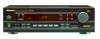
Pioneer VSX 108 Support Question
Pioneer VSX 108 Support Question
Find answers below for this question about Pioneer VSX 108 - AV Receiver.Need a Pioneer VSX 108 manual? We have 1 online manual for this item!
Question posted by dstngreenwood on October 7th, 2014
How Do I Reset The Overload On My Pioneer Vsx 108
The person who posted this question about this Pioneer product did not include a detailed explanation. Please use the "Request More Information" button to the right if more details would help you to answer this question.
Current Answers
Related Pioneer VSX 108 Manual Pages
Service Manual - Page 1
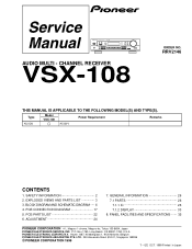
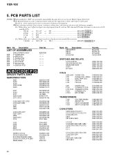
... AND SCHEMATIC DIAGRAM ..... 6 4. PCB CONNECTION DIAGRAM 17 5.
PCB PARTS LIST 22 6. PANEL FACILITIES AND SPECIFICATIONS ....... 35
PIONEER CORPORATION 4-1, Meguro 1-chome, Meguro-ku, Tokyo 153-8654, Japan
PIONEER ELECTRONICS SERVICE, INC. CHANNEL RECEIVER
VSX-108
ORDER NO. SAFETY INFORMATION 2 2. EXPLODED VIEWS AND PARTS LIST 3 3. GENERAL INFORMATION 26 7.1 PARTS 26 7.1.1 IC...
Service Manual - Page 2

...
not be obtained by them necessarily can adversely affect the safety and reliability of , PIONEER Service Manual may void the warranty.
A subscription to do -ityourselfer. WARNING This product... for the casual do so and refer the repair to a qualified service technician.
VSX-108
1. Product Safety is intended for the continued protection of the appliance directly into a...
Service Manual - Page 3
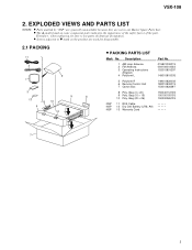
VSX-108
2. EXPLODED VIEWS AND PARTS LIST
• NOTES: Parts marked by "NSP" are generally unavailable because they are used for disassembly.
2.1 PACKING
11 2
9 1
3
13 8 10
4
5
6
12
&#...
Service Manual - Page 5
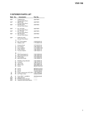
...
30 AC Power Cord
02360040009S
NSP NSP NSP
31 Fuse (F801 : 4A/250V) 32 Metal Washer 33 PCB Mounting Bracket 34 Heatsink Mounting Bracket
05005020402S
VSX-108
5 Description
Part No.
• EXTERIOR PARTS LIST
Mark No.
Service Manual - Page 6
FM IF REQ.
1
2
3
4
VSX-108
3. IND EO AM SIG. MONO
- GND AM/FM IF
12
10 9 8 7 6 5 4 3 2 1
L
...SR GND
CN7
1 2 3 4 5 6 7
B MAIN PCB B 1/2, B 2/2
V1 FL TUBE 04991693-001
1
2
CONTROL OUT
IC703
06104421-000
D
IR Receiver
G DISPLAY PCB
6
1
2
3
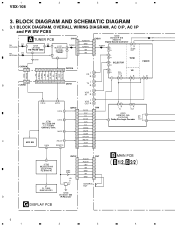
4 BLOCK DIAGRAM AND SCHEMATIC DIAGRAM
3.1 BLOCK DIAGRAM, OVERALL WIRING DIAGRAM, AC O/P, AC I/P
A
and PW SW PCBS
FM ANTENNA...
Service Manual - Page 7
...
C823 R821 0.01/250V 120/1W
AC120V
W4
60Hz
NEUTRAL
T1
POWER
D
TRANSFORMER 01801088522S
AC O/P PCB
E AC I/P PCB
R820
3M3
D
AC POWER CORD 02360040009S
DEF 7
5
6
7
8
5
6
7
8
VSX-108
Note : When ordering service parts, be sure to refer to "EXPLODED VIEWS and PARTS LIST" or "PCB PARTS LIST".
A
• NOTE FOR FUSE REPLACEMENT
CAUTION...
Service Manual - Page 10
1
2
VSX-108
3.3 MAIN PCB (1/2)
A JACK4
JACK3
JACK2 IN
B
3
4
B 1/2 MAIN PCB
A CN102
CN201
T
IC203 00262419-010
(M62419)
VCR
T
OUT JACK1
C
05208000-000
IC201
00201041-040
S
(LV1041M)
C
D
10 B 1/2
1
2
3
4
Service Manual - Page 11
5
G CN702
CN6
6
B 2/2
7
8
VSX-108
CN7
G CN707
Q213 00310536-046
C CN14A
A
Q212
00310536-046
R L GND L-SP R-ST SP-OFF
CN14
S
S C
C
Q203 00302576-040
Q204 00303576-040
IC204 STK407-070
L201 ...
Service Manual - Page 12
1
2
3
4
VSX-108
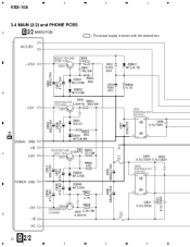
3.4 MAIN (2/2) and PHONE PCBS
A
B 2/2 MAIN PCB
: The power supply is shown with the marked box. B
B 1/2
C
D
12 B 2/2
1
2
3
4
Service Manual - Page 15
... : STEREO SW18 : LOUDNESS SW19 : STATION + SW20 : TUNING + SW21 : FM SW22 : BASS +
SW23 : TREBLE + SW26 : STATION SW27 : TUNING SW29 : BASS SW30 : TREBLE SW31 : BALANCE L SW32 : BALANCE R
8
VSX-108
A
B 1/2
CN7
B 1/2
CN6
B
A CN701A
A CN708A
C
D
G 15
5
6
7
8
Service Manual - Page 17
... to check with resistor
DGS
D G SD G S
Field effect transistor
A TUNER PCB
Resistor array
3-terminal
regulator
Q102
B
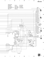
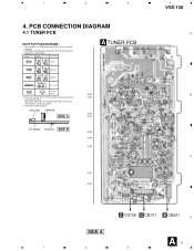
3. PCB CONNECTION DIAGRAM
4.1 TUNER PCB
A
NOTE FOR PCB DIAGRAMS :
1. 1
2
3
4
VSX-108
4. Part numbers in PCB diagrams match those in the schematic diagrams.
2.
Service Manual - Page 18
1
2
3
4
VSX-108
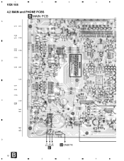
4.2 MAIN and PHONE PCBS
B MAIN PCB
A
Q212 Q213
Q209 Q211 IC208
Q203 Q204 IC203
IC204
B
Q205 Q206
IC201
Q201 Q202
IC205
C
IC202
Q208 Q207
Q402 Q401
Q801 Q804
D
B 18 1
J7 J5 J6
D
D CN207A
2
3
4
Service Manual - Page 21

5
6
7
8
VSX-108
A
08 07
B
B CN7 B CN6
AC1.9V AC1.9V -25V +5V GND SR OUT GND J718 DATA CLK E1 DATA CLK E2 DGND MUTE OVER SP-...
Service Manual - Page 22
... COIL
01500030-006 01500102-001 01500393-001 01705037-350 01706036-350
L201 F103 F101,F102 F104 F1010
CHOKE COIL CERAMIC FILTER CERAMIC FILTER CERAMIC DTS. VSX-108
Mark No. Ex.1 When there are 2 effective digits (any digit apart from 0), such as shown in high precision metal film resistors).
5.62k Ω → 562...
Service Manual - Page 23
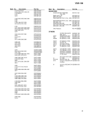
... CEAT101M35
CEAT102M10 CEAT1R0M50 CEAT220M50 CEAT221M10 CEAT222M25
CEAT2R2M50 CEAT330M16 CEAT3R3M50 CEAT470M10 CEAT470M10
CEAT470M25 CEAT470M35 CEAT471M10 CEAT4R7M50 CEAT4R7M50
CEAT4R7M50 CEAT4R7M50 CEAT4R7M50 CEATR33M50 CEATR47M50
CEATR47M50 01410200-003
VSX-108
Mark No. RESISTORS
R278,R279,R287,R289,R803
00510101-321
(10Ω, 2W)
R808 (2.2kΩ, 1W)
00510222-311
R805 (27Ω, 2W...
Service Manual - Page 24
VSX-108
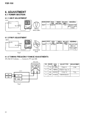
6. ADJUSTMENT
6.1 TUNER SECTION
6.1.1 AM IF ADJUSTMENT
Fig.1
6.1.2 FM IF ADJUSTMENT
Fig.2
6.1.3 TUNING FREQUENCY RANGE ADJUSTMENTS
(FM, AM) DC Voltmeter.........Connect to TP1 and GND
Fig.3
24
Service Manual - Page 25
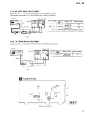
6.1.4 AM TRACKING ADJUSTMENT
Signal Generator.........Connects to the FM ANT Jack (FM IN) through the Loop Antenna. VSX-108
Fig.4
6.1.5 FM TRACKING ADJUSTMENT
Signal Generator.........Connects to the AM ANT.
Fig.5
A TUNER PCB
T104
IC102
Pin 23
TP3
Pin 24
TP4
T102
TP1 R101 ...
Service Manual - Page 26
...
18
17 16
ALC BUFF.
AGC
3rd 5th
DECODER ANT1-BIRDIE
P-DET. TUNING DRIVE
STEREO DRIVE
GND
Vcc
1
2
3
4
5
6
7
8
9
10
11
12
13
14
15
26
VSX-108
7.
AM
AM
MIX RF AMP.
Service Manual - Page 27
...
00206458-040 (LA6458S) (MAIN PCB : IC202, IC208)
• Dual Operational Amplifier IC
• Block Diagram
1
2
3
4
5
6
7
8
9
VCC
VOUT1
VIN1
VIN1
VEE
VIN2
VIN2
VOUT2
VCC
27
VSX-108
• Pin Function
No. Function
1 FM IF input
2 AM MIX output
3 FM IF input by-pass
4 AM IF input
5 GND
6 TU-LED
7 ST-LED and...
Service Manual - Page 28
...;OP-OUT
VOL-REF S•OP-OUT
S•OP-NF S•OP-IN S•VOL-OUT OP-VREF S•VOL-IN
S-OUT DC-CUT
28 VSX-108
00201041-040 (LV1041M) (MAIN PCB : IC201)
• Dolby Pro-Logic Decoder IC
• Block Diagram
R-BPF3 DCCUT1 L-R•RECT DCCUT2 L+R•RECT VCS-TH VCS...
Similar Questions

How Do You Reset The Vsx- D511 Receiver?
Any help on how to reset the pioneer vsx-D511 receiver?
Any help on how to reset the pioneer vsx-D511 receiver?
(Posted by kylecook2015 5 years ago)

Sound Failure On Vsx-108.
The sound on the "TV" setting has failed. The other functions work (FM, AM, VCR). Is there a fuse or...
The sound on the "TV" setting has failed. The other functions work (FM, AM, VCR). Is there a fuse or...
(Posted by wjg4 6 years ago)

How To Reset Pioneer Vsx-519v
(Posted by dembilly 10 years ago)

Displaying Dc Out
my pioneer vsx-108 is displaying dc out and wont do anything else
my pioneer vsx-108 is displaying dc out and wont do anything else
(Posted by ashlyb31 11 years ago)