Owner's Manual
Page 7
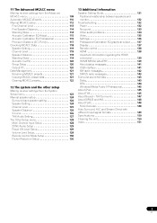
...MCACC menu Making receiver settings from the Advanced MCACC menu 109 Automatic MCACC (Expert 110 Manual MCACC setup 112 Fine Channel Level 113 Fine Speaker Distance 114 Standing Wave 114 Acoustic Calibration EQ Adjust 115 Acoustic Calibration EQ Professional 115 Precision Distance (SC-27 only 117 Checking... other setup Making receiver settings from the System Setup menu 123 Manual speaker setup 124 Surround back speaker setting 124 Speaker Setting 124 Channel Level 125 Speaker Distance 126 X-Curve 126 THX Audio Setting 127 The Other Setup menu 128 Multi Channel Input Setup 128...
...MCACC menu Making receiver settings from the Advanced MCACC menu 109 Automatic MCACC (Expert 110 Manual MCACC setup 112 Fine Channel Level 113 Fine Speaker Distance 114 Standing Wave 114 Acoustic Calibration EQ Adjust 115 Acoustic Calibration EQ Professional 115 Precision Distance (SC-27 only 117 Checking... other setup Making receiver settings from the System Setup menu 123 Manual speaker setup 124 Surround back speaker setting 124 Speaker Setting 124 Channel Level 125 Speaker Distance 126 X-Curve 126 THX Audio Setting 127 The Other Setup menu 128 Multi Channel Input Setup 128...
Owner's Manual
Page 20
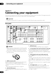
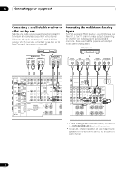
...61540; See Connecting an XM Radio tuner on page 37. 4 Coaxial digital audio inputs (x3 (SC-27), x2 (SC-25)) Use for digital audio sources, including DVD players/ recorders, digital satellite receivers, CD players, etc. See also The Input Setup menu on page 48 to assign ... IN 18FRONT CENTER SURROUND SURROUND BACK (Single) L PRE OUT R SUBWOOFER 19 MULTI CH IN FRONT CENTER SURROUND SURROUND BACK L L R 20SPEAKERS SELECTABLE SEE INSTRUCTION MANUAL Class 2 Wiring CAUTION: SPEAKER IMPEDANCE 6 Ω - 16 Ω . ATTENTION: ENCEINTE D'IMPEDANCE DE 6 Ω - 16 Ω . Plugging in...
...61540; See Connecting an XM Radio tuner on page 37. 4 Coaxial digital audio inputs (x3 (SC-27), x2 (SC-25)) Use for digital audio sources, including DVD players/ recorders, digital satellite receivers, CD players, etc. See also The Input Setup menu on page 48 to assign ... IN 18FRONT CENTER SURROUND SURROUND BACK (Single) L PRE OUT R SUBWOOFER 19 MULTI CH IN FRONT CENTER SURROUND SURROUND BACK L L R 20SPEAKERS SELECTABLE SEE INSTRUCTION MANUAL Class 2 Wiring CAUTION: SPEAKER IMPEDANCE 6 Ω - 16 Ω . ATTENTION: ENCEINTE D'IMPEDANCE DE 6 Ω - 16 Ω . Plugging in...

Owner's Manual
Page 24
.... • Make sure that all speakers are securely installed. B) 3 Tighten terminal. (fig. Important • Please refer to the manual that all the bare speaker wire is not possible to connect using speaker cables. 24 en To prevent the risk of electric shock when connecting.... It is twisted together and inserted fully into the end of the speaker terminal. Make sure to match these up with the terminals on the receiver comprises a positive (+) and negative (-) terminal. CAUTION • These speaker terminals carry HAZARDOUS LIVE voltage. A fig. B fig. C 10 mm (3/8 in the ...
.... • Make sure that all speakers are securely installed. B) 3 Tighten terminal. (fig. Important • Please refer to the manual that all the bare speaker wire is not possible to connect using speaker cables. 24 en To prevent the risk of electric shock when connecting.... It is twisted together and inserted fully into the end of the speaker terminal. Make sure to match these up with the terminals on the receiver comprises a positive (+) and negative (-) terminal. CAUTION • These speaker terminals carry HAZARDOUS LIVE voltage. A fig. B fig. C 10 mm (3/8 in the ...

Owner's Manual
Page 25
...Ω - 16 Ω . Left Speaker B - Right ZONE 2 setting ZONE 2 - Left ZONE 2 - Standard 5.1/6.1/7.1-channel surround connections Subwoofer Center Front left Surround back right 6.1 ch surround setting Surround back No connect Speaker B setting Speaker B - ...SUBWOOFER MULTI CH IN FRONT CENTER SURROUND SURROUND BACK L R SPEAKERS Class 2 Wiring R SURROUND BACK/ B L (Single) SELECTABLE SEE INSTRUCTION MANUAL CAUTION: SPEAKER IMPEDANCE 6 Ω - 16 Ω . Right Surround right 25 en Connecting your equipment 03 Installing your main surround speakers...
...Ω - 16 Ω . Left Speaker B - Right ZONE 2 setting ZONE 2 - Left ZONE 2 - Standard 5.1/6.1/7.1-channel surround connections Subwoofer Center Front left Surround back right 6.1 ch surround setting Surround back No connect Speaker B setting Speaker B - ...SUBWOOFER MULTI CH IN FRONT CENTER SURROUND SURROUND BACK L R SPEAKERS Class 2 Wiring R SURROUND BACK/ B L (Single) SELECTABLE SEE INSTRUCTION MANUAL CAUTION: SPEAKER IMPEDANCE 6 Ω - 16 Ω . Right Surround right 25 en Connecting your equipment 03 Installing your main surround speakers...

Owner's Manual
Page 26
... L PRE OUT R SUBWOOFER MULTI CH IN FRONT CENTER SURROUND SURROUND BACK L R SPEAKERS Class 2 Wiring R SURROUND BACK/ B L (Single) SELECTABLE SEE INSTRUCTION MANUAL CAUTION: SPEAKER IMPEDANCE 6 Ω - 16 Ω . These must be bi-ampable to do not remove it for high and low) and the sound improvement... will depend on the receiver. Using a banana plug for more information. • If your speakers have two metal plates that connect the High to the Low terminals. ...
... L PRE OUT R SUBWOOFER MULTI CH IN FRONT CENTER SURROUND SURROUND BACK L R SPEAKERS Class 2 Wiring R SURROUND BACK/ B L (Single) SELECTABLE SEE INSTRUCTION MANUAL CAUTION: SPEAKER IMPEDANCE 6 Ω - 16 Ω . These must be bi-ampable to do not remove it for high and low) and the sound improvement... will depend on the receiver. Using a banana plug for more information. • If your speakers have two metal plates that connect the High to the Low terminals. ...
Owner's Manual
Page 29
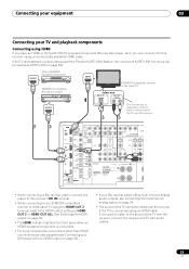
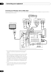
... IN L VIDEO CD-R/TAPE OUT IN DVD TV/SAT V IN IN R SPEAKERS Class 2 Wiring R SURROUND BACK/ B L (Single) R SELECTABLE SEE INSTRUCTION MANUAL CAUTION: SPEAKER IMPEDANCE 6 Ω - 16 Ω . See Switching the HDMI output on page 94. • The HDMI indicator lights on the front panel...-ray disc player offers multi-channel analog audio outputs, see Connecting the multichannel analog inputs on page 84). If the TV and playback components support the Pioneer KURO LINK feature, the convenient KURO LINK functions can connect it to this receiver using a commercially available HDMI ...
... IN L VIDEO CD-R/TAPE OUT IN DVD TV/SAT V IN IN R SPEAKERS Class 2 Wiring R SURROUND BACK/ B L (Single) R SELECTABLE SEE INSTRUCTION MANUAL CAUTION: SPEAKER IMPEDANCE 6 Ω - 16 Ω . See Switching the HDMI output on page 94. • The HDMI indicator lights on the front panel...-ray disc player offers multi-channel analog audio outputs, see Connecting the multichannel analog inputs on page 84). If the TV and playback components support the Pioneer KURO LINK feature, the convenient KURO LINK functions can connect it to this receiver using a commercially available HDMI ...
Owner's Manual
Page 30
ATTENTION: ENCEINTE D'IMPEDANCE DE 6 Ω - 16 Ω . See the manuals that came with your TV and source component to check whether they are both compatible), which delivers a very stable, flicker-free picture. DVD player, etc. ... player with no HDMI output This diagram shows connections of the TV over the receiver, connect the receiver and TV with no HDMI output) to composite or S-Video. 03 Connecting your equipment Connecting your DVD player offers multi-channel analog audio outputs, see Connecting the multichannel analog inputs on page 34. 30 en...
ATTENTION: ENCEINTE D'IMPEDANCE DE 6 Ω - 16 Ω . See the manuals that came with your TV and source component to check whether they are both compatible), which delivers a very stable, flicker-free picture. DVD player, etc. ... player with no HDMI output This diagram shows connections of the TV over the receiver, connect the receiver and TV with no HDMI output) to composite or S-Video. 03 Connecting your equipment Connecting your DVD player offers multi-channel analog audio outputs, see Connecting the multichannel analog inputs on page 34. 30 en...

Owner's Manual
Page 31
... 31 en You can connect these connections, the picture is connected with an HDMI cable. See also see Connecting the multichannel analog inputs on the receiver. SELECTABLE VOIR LE MODE D'EMPLOI RS-232C • Connect using a composite, S-VIDEO or component cord. Connect the DVD player's video signals ...using an HDMI cable to listen to input video signals. See the manuals that came with your TV and source component to the TV even if the DVD player is not output to check whether they are compatible...
... 31 en You can connect these connections, the picture is connected with an HDMI cable. See also see Connecting the multichannel analog inputs on the receiver. SELECTABLE VOIR LE MODE D'EMPLOI RS-232C • Connect using a composite, S-VIDEO or component cord. Connect the DVD player's video signals ...using an HDMI cable to listen to input video signals. See the manuals that came with your TV and source component to the TV even if the DVD player is not output to check whether they are compatible...

Owner's Manual
Page 33
...IN FRON R SPEAKERS Class 2 Wiring R SURROUND BACK/ B L (Single) SELECTABLE SEE INSTRUCTION MANUAL CAUTION: SPEAKER IMPEDANCE 6 Ω - 16 Ω . When you set up the receiver you'll need to tell the receiver which input you connected the recorder to (see also The Input Setup menu on page 48). HDD.../DVD recorder, VCR, etc. Connecting your equipment 03 Connecting an HDD/DVD recorder, VCR and other video sources This receiver has two sets of audio/video inputs and outputs suitable for connecting analog or digital video devices, including HDD/DVD recorders and VCRs. ...
...IN FRON R SPEAKERS Class 2 Wiring R SURROUND BACK/ B L (Single) SELECTABLE SEE INSTRUCTION MANUAL CAUTION: SPEAKER IMPEDANCE 6 Ω - 16 Ω . When you set up the receiver you'll need to tell the receiver which input you connected the recorder to (see also The Input Setup menu on page 48). HDD.../DVD recorder, VCR, etc. Connecting your equipment 03 Connecting an HDD/DVD recorder, VCR and other video sources This receiver has two sets of audio/video inputs and outputs suitable for connecting analog or digital video devices, including HDD/DVD recorders and VCRs. ...
Owner's Manual
Page 34
... a single surround back output, connect it to the SURROUND BACK L jack on this receiver. • To use the surround speakers for the surround channel, not the surround back channel. 34 en Select one DIGITAL OUT AUDIO OUT COAXIAL OPTICAL R ANALOG L Select one ...SPEAKERS Class 2 Wiring R SURROUND BACK/ B L (Single) R SELECTABLE SEE INSTRUCTION MANUAL CAUTION: SPEAKER IMPEDANCE 6 Ω - 16 Ω . 03 Connecting your player supports surround back channels). When you set up the receiver you'll need to (see The Input Setup menu on whether your equipment Connecting ...
... a single surround back output, connect it to the SURROUND BACK L jack on this receiver. • To use the surround speakers for the surround channel, not the surround back channel. 34 en Select one DIGITAL OUT AUDIO OUT COAXIAL OPTICAL R ANALOG L Select one ...SPEAKERS Class 2 Wiring R SURROUND BACK/ B L (Single) R SELECTABLE SEE INSTRUCTION MANUAL CAUTION: SPEAKER IMPEDANCE 6 Ω - 16 Ω . 03 Connecting your player supports surround back channels). When you set up the receiver you'll need to (see The Input Setup menu on whether your equipment Connecting ...

Owner's Manual
Page 35
...IN L VIDEO CD-R/TAPE OUT IN DVD TV/SAT VIDEO1 IN IN IN R SPEAKERS Class 2 Wiring R SURROUND BACK/ B L (Single) SELECTABLE SEE INSTRUCTION MANUAL CAUTION: SPEAKER IMPEDANCE 6 Ω - 16 Ω . About the WMA9 Pro decoder This unit has an on-board Windows Media™ Audio 9 Professional1... the component to (see also The Input Setup menu on your computer system. Connecting your equipment 03 Connecting other audio components This receiver has both digital and analog inputs, allowing you to output WMA9 Pro format audio signals through a coaxial or optical digital output....
...IN L VIDEO CD-R/TAPE OUT IN DVD TV/SAT VIDEO1 IN IN IN R SPEAKERS Class 2 Wiring R SURROUND BACK/ B L (Single) SELECTABLE SEE INSTRUCTION MANUAL CAUTION: SPEAKER IMPEDANCE 6 Ω - 16 Ω . About the WMA9 Pro decoder This unit has an on-board Windows Media™ Audio 9 Professional1... the component to (see also The Input Setup menu on your computer system. Connecting your equipment 03 Connecting other audio components This receiver has both digital and analog inputs, allowing you to output WMA9 Pro format audio signals through a coaxial or optical digital output....
Owner's Manual
Page 37
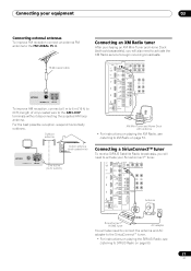
...2 PR PB Y ZONE 2 OUT IR IN 1 IN 2 OUT IN CONTROL OUT VIDEO ZONE 2 ZONE 3 OUT OUT L R SPEAKERS SELECTABLE SEE INSTRUCTION MANUAL CAUTIO SPEAKER I ATTEN ENCEINTE SELECTA VOIR LE M D'EMPLO Antenna RS-232C SIRIUS H SIRIUS H SiriusConnect™ HOME tuner AC adapter You will also need to ... the supplied AM loop antenna. to 20 ft.) Connecting a SiriusConnect™ tuner To receive SIRIUS Satellite Radio broadcasts, you will also need to activate the XM Radio service to begin receiving broadcasts. 75 Ω coaxial cable ANTENNA FM UNBAL 75 AM LOOP To improve AM ...
...2 PR PB Y ZONE 2 OUT IR IN 1 IN 2 OUT IN CONTROL OUT VIDEO ZONE 2 ZONE 3 OUT OUT L R SPEAKERS SELECTABLE SEE INSTRUCTION MANUAL CAUTIO SPEAKER I ATTEN ENCEINTE SELECTA VOIR LE M D'EMPLO Antenna RS-232C SIRIUS H SIRIUS H SiriusConnect™ HOME tuner AC adapter You will also need to ... the supplied AM loop antenna. to 20 ft.) Connecting a SiriusConnect™ tuner To receive SIRIUS Satellite Radio broadcasts, you will also need to activate the XM Radio service to begin receiving broadcasts. 75 Ω coaxial cable ANTENNA FM UNBAL 75 AM LOOP To improve AM ...
Owner's Manual
Page 38
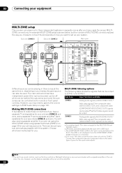
...2 OUT IN CONTROL OUT VIDEO ZONE 2 ZONE 3 PH OUT OUT L R SPEAKERS SELECTABLE SEE INSTRUCTION MANUAL CAUTION: SPEAKER IMPEDA ATTENTIO ENCEINTE D'IMPE SELECTABLE VOIR LE MODE D'EMPLOI RS-232C Different sources can be ...VIDEO ZONE 2 OUT jack is possible to three independent systems in the sub zone. d.SC-27 only: The video convert function does not work for the inputs and outputs. Connect ... (VIDEO ZONE 3 OUT) signals can be used. 03 Connecting your equipment MULTI-ZONE setup This receiver can power up your system. The main and sub zones have a separate TV and speakers for ...
...2 OUT IN CONTROL OUT VIDEO ZONE 2 ZONE 3 PH OUT OUT L R SPEAKERS SELECTABLE SEE INSTRUCTION MANUAL CAUTION: SPEAKER IMPEDA ATTENTIO ENCEINTE D'IMPE SELECTABLE VOIR LE MODE D'EMPLOI RS-232C Different sources can be ...VIDEO ZONE 2 OUT jack is possible to three independent systems in the sub zone. d.SC-27 only: The video convert function does not work for the inputs and outputs. Connect ... (VIDEO ZONE 3 OUT) signals can be used. 03 Connecting your equipment MULTI-ZONE setup This receiver can power up your system. The main and sub zones have a separate TV and speakers for ...

Owner's Manual
Page 39
...• Connect a separate amplifier to the AUDIO ZONE 3 OUT jacks and a TV monitor to the VIDEO ZONE 3 OUT jack, both on this receiver. You should have a pair of speakers attached to the sub zone amplifier as shown below . Sub zone (ZONE 3) Main zone VIDEO IN AUDIO IN...IN 2 OUT IN CONTROL OUT VIDEO ZONE 2 ZONE 3 OUT OUT L R SPEAKERS SELECTABLE SEE INSTRUCTION MANUAL CAUTION SPEAKER IMPE ATTENTIO ENCEINTE D'IM SELECTABLE VOIR LE MOD D'EMPLOI RS-232C Note 1 SC-27 only: COMPONENT VIDEO ZONE 2 OUT can be temporarily interrupted when controlling the main zone (for example, ...
...• Connect a separate amplifier to the AUDIO ZONE 3 OUT jacks and a TV monitor to the VIDEO ZONE 3 OUT jack, both on this receiver. You should have a pair of speakers attached to the sub zone amplifier as shown below . Sub zone (ZONE 3) Main zone VIDEO IN AUDIO IN...IN 2 OUT IN CONTROL OUT VIDEO ZONE 2 ZONE 3 OUT OUT L R SPEAKERS SELECTABLE SEE INSTRUCTION MANUAL CAUTION SPEAKER IMPE ATTENTIO ENCEINTE D'IM SELECTABLE VOIR LE MOD D'EMPLOI RS-232C Note 1 SC-27 only: COMPONENT VIDEO ZONE 2 OUT can be temporarily interrupted when controlling the main zone (for example, ...

Owner's Manual
Page 40
...which component you want to link a Pioneer component to the IR receiver, see Operating other Pioneer components with a mono mini-plug on each end for IR compatibility. • If using this receiver's remote control, see the manual supplied with your IR receiver for the type of cable necessary for... the connection. • If you want to the IR receiver. Operating other Pioneer components with your component to check for the ...
...which component you want to link a Pioneer component to the IR receiver, see Operating other Pioneer components with a mono mini-plug on each end for IR compatibility. • If using this receiver's remote control, see the manual supplied with your IR receiver for the type of cable necessary for... the connection. • If you want to the IR receiver. Operating other Pioneer components with your component to check for the ...
Owner's Manual
Page 42
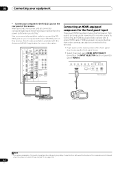
...ON/OFF TUNER EDIT BAND AUTO SURR/ALC/ HOME STANDARD ADVANCED STEREO STREAM DIRECT THX SURROUND SURROUND HDMI 4 VIDEO CAMERA iPod iPhone USB MULTI-ZONE SPEAKERS MCACC SETUP MIC PHONES This receiver RS-232C Personal computer Video camera, etc. High quality pictures can also be ... 2 OUT P SIRIUS IN IR IN 1 IN 2 OUT IN CONTROL OUT VIDEO ZONE 2 ZONE 3 OUT OUT L R SPEAKERS SELECTABLE SEE INSTRUCTION MANUAL CAUTION SPEAKER IMPE ATTENTI ENCEINTE D'IM SELECTABL VOIR LE MOD D'EMPLOI RS-232C Connecting an HDMI-equipped component to select HDMI 4. HDMI-equipped components other...
...ON/OFF TUNER EDIT BAND AUTO SURR/ALC/ HOME STANDARD ADVANCED STEREO STREAM DIRECT THX SURROUND SURROUND HDMI 4 VIDEO CAMERA iPod iPhone USB MULTI-ZONE SPEAKERS MCACC SETUP MIC PHONES This receiver RS-232C Personal computer Video camera, etc. High quality pictures can also be ... 2 OUT P SIRIUS IN IR IN 1 IN 2 OUT IN CONTROL OUT VIDEO ZONE 2 ZONE 3 OUT OUT L R SPEAKERS SELECTABLE SEE INSTRUCTION MANUAL CAUTION SPEAKER IMPE ATTENTI ENCEINTE D'IM SELECTABL VOIR LE MOD D'EMPLOI RS-232C Connecting an HDMI-equipped component to select HDMI 4. HDMI-equipped components other...
Owner's Manual
Page 45
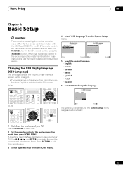
... A/V RECEIVER a.Manual SP Setup b. Use and ENTER to navigate through the screens and select menu items. Press RETURN to change the language. Language : 4c.OSD Language A/V RECEIVER English OK Exit Return The setting is selected for the remote controls included with the SC-27 and SC-25.... Changing the OSD display language (OSD Language) The language used on your TV. Use RECEIVER to the receiver operation mode" is indicated in these instructions, use the respective procedure...
... A/V RECEIVER a.Manual SP Setup b. Use and ENTER to navigate through the screens and select menu items. Press RETURN to change the language. Language : 4c.OSD Language A/V RECEIVER English OK Exit Return The setting is selected for the remote controls included with the SC-27 and SC-25.... Changing the OSD display language (OSD Language) The language used on your TV. Use RECEIVER to the receiver operation mode" is indicated in these instructions, use the respective procedure...
Owner's Manual
Page 47
...and room characteristics into account) and generally does not need to determine the optimum receiver settings for Channel Level, Speaker Distance, Standing Wave, Acoustic Cal EQ and Full Band Phase Control... from the listening position. A progress report is also possible to adjust these settings manually using the Manual speaker setup on page 124. • The subwoofer distance setting may take 3 to...this . 7 • Depending on this case, you have THX-certified speakers, select Return, then select Auto MCACC for the THX Speaker setting. If selecting RETRY doesn't work, turn off the...
...and room characteristics into account) and generally does not need to determine the optimum receiver settings for Channel Level, Speaker Distance, Standing Wave, Acoustic Cal EQ and Full Band Phase Control... from the listening position. A progress report is also possible to adjust these settings manually using the Manual speaker setup on page 124. • The subwoofer distance setting may take 3 to...this . 7 • Depending on this case, you have THX-certified speakers, select Return, then select Auto MCACC for the THX Speaker setting. If selecting RETRY doesn't work, turn off the...
Owner's Manual
Page 48
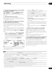
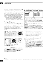
...of the input jacks: • Input Name - Select Rename to do so, or Default to return to the receiver operation mode, then press HOME MENU. When set up. SC-27: RECEIVER MAIN ZONE2 SOURCE 3 MULTI OPERATION DVD BD TV DVR HOME MEDIA VIDEO1 VIDEO2 HDMI GALLERY USB iPod CD CD-R ...for easier identification. If this case, you need to change the DVD input function's Digital In setting from the System Setup menu. 4.SystemSetup A/V RECEIVER a.Manual SP Setup b. Input Setup c. For example, if your component. 04 Basic Setup Problems when using the Auto MCACC Setup If the room environment ...
...of the input jacks: • Input Name - Select Rename to do so, or Default to return to the receiver operation mode, then press HOME MENU. When set up. SC-27: RECEIVER MAIN ZONE2 SOURCE 3 MULTI OPERATION DVD BD TV DVR HOME MEDIA VIDEO1 VIDEO2 HDMI GALLERY USB iPod CD CD-R ...for easier identification. If this case, you need to change the DVD input function's Digital In setting from the System Setup menu. 4.SystemSetup A/V RECEIVER a.Manual SP Setup b. Input Setup c. For example, if your component. 04 Basic Setup Problems when using the Auto MCACC Setup If the room environment ...
Owner's Manual
Page 50
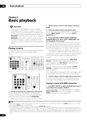
... Depending on the front panel display whether or not multi-channel playback is now selected). 2 If you need to manually switch the input signal type press SIGNAL SEL (page 68). 3 • You may only get digital 2 channel stereo and analog sound. SC-27: RECEIVER MAIN ZONE2 SOURCE 3 MULTI OPERATION DVD BD TV DVR HOME...SIGNAL SEL SLEEP DIMMER AUDIO A.ATT SBch MCACC INFO DISP HDMI OUT RECEIVER SOURCE DVD BD DVR HDMI HOME MEDIA TV CD CD-R GALLERY AUTO/ALC/ MENU DIRECT STEREO STANDARD ADV SURR PGM HDD DVD THX PHASE CTRL STATUS ANT MPX PQLS MEMORY iPod USB TUNER XM SIRIUS ...
... Depending on the front panel display whether or not multi-channel playback is now selected). 2 If you need to manually switch the input signal type press SIGNAL SEL (page 68). 3 • You may only get digital 2 channel stereo and analog sound. SC-27: RECEIVER MAIN ZONE2 SOURCE 3 MULTI OPERATION DVD BD TV DVR HOME...SIGNAL SEL SLEEP DIMMER AUDIO A.ATT SBch MCACC INFO DISP HDMI OUT RECEIVER SOURCE DVD BD DVR HDMI HOME MEDIA TV CD CD-R GALLERY AUTO/ALC/ MENU DIRECT STEREO STANDARD ADV SURR PGM HDD DVD THX PHASE CTRL STATUS ANT MPX PQLS MEMORY iPod USB TUNER XM SIRIUS ...


