Owner's Manual
Page 3
PWM-F110 Table of Contents Warning Statements ...- 4 Parts List ...- 6 Installation Tools ...- 6 Mounting Bracket Installation ...- 7 Wall Stud Location ...- 10 Installing the Flat Panel Display ...- 14 Technical Specifications ...- 16 Warranty ...- 17 Contact Premier Mounts ...- 17 Notes ...- 18 - Installation Manual Page - 3 -
PWM-F110 Table of Contents Warning Statements ...- 4 Parts List ...- 6 Installation Tools ...- 6 Mounting Bracket Installation ...- 7 Wall Stud Location ...- 10 Installing the Flat Panel Display ...- 14 Technical Specifications ...- 16 Warranty ...- 17 Contact Premier Mounts ...- 17 Notes ...- 18 - Installation Manual Page - 3 -
Owner's Manual
Page 6
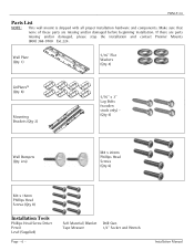
PWM-F110 Parts List NOTE: This wall mount is shipped with all proper installation hardware and components. Wall Plate (Qty 1) 5/16" Flat Washers (Qty 4) GriPlates™ (Qty 8) Mounting Brackets (Qty 2) 5/16" x 3" Lag Bolts (wooden studs only) - (Qty 4) Wall Bumpers (Qty 2ea) M8 x 20mm Phillips Head Screws (Qty 6) M4 x 16mm Phillips Head Screws (Qty 8) Installation Tools Phillips Head Screw ...Socket and Wrench Installation Manual Make sure that none of these parts are parts missing and/or damaged, please stop the installation and contact Premier Mounts (800) 368-9700 Ext.224.
PWM-F110 Parts List NOTE: This wall mount is shipped with all proper installation hardware and components. Wall Plate (Qty 1) 5/16" Flat Washers (Qty 4) GriPlates™ (Qty 8) Mounting Brackets (Qty 2) 5/16" x 3" Lag Bolts (wooden studs only) - (Qty 4) Wall Bumpers (Qty 2ea) M8 x 20mm Phillips Head Screws (Qty 6) M4 x 16mm Phillips Head Screws (Qty 8) Installation Tools Phillips Head Screw ...Socket and Wrench Installation Manual Make sure that none of these parts are parts missing and/or damaged, please stop the installation and contact Premier Mounts (800) 368-9700 Ext.224.
Owner's Manual
Page 10
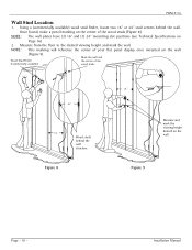
.... 1166"" 16" Wood studs behind the wall. Wood Stud Finder (Commercially available) Mark the wall and the center of your flat panel display once mounted on the center of the wood studs (Figure 8). Figure 9 Page - 10 - NOTE: The wall plates have (3) 16" and (1) 24" mounting slot positions (see Technical Specifications on the wall. PWM-F110 Wall Stud Location 1. Once found, make...
.... 1166"" 16" Wood studs behind the wall. Wood Stud Finder (Commercially available) Mark the wall and the center of your flat panel display once mounted on the center of the wood studs (Figure 8). Figure 9 Page - 10 - NOTE: The wall plates have (3) 16" and (1) 24" mounting slot positions (see Technical Specifications on the wall. PWM-F110 Wall Stud Location 1. Once found, make...
Owner's Manual
Page 14
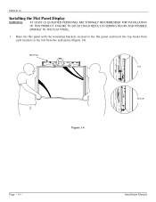
Raise the flat panel with the mounting brackets secured to the flat panel and insert the top hooks from each bracket to the rod from the wall plates (Figure 14). Wall Plate Top Figure 14 Bottom Page - 14 - Installation Manual PWM-F110 Installing the Flat Panel Display WARNING: AT LEAST (2) QUALIFIED PERSONNEL ARE STRONGLY RECOMMENDED FOR INSTALLATION OF THIS PRODUCT. FAILURE TO DO SO COULD RESULT IN SERIOUS INJURY AND POSSIBLE DAMAGE TO THE FLAT PANEL. 1.
Raise the flat panel with the mounting brackets secured to the flat panel and insert the top hooks from each bracket to the rod from the wall plates (Figure 14). Wall Plate Top Figure 14 Bottom Page - 14 - Installation Manual PWM-F110 Installing the Flat Panel Display WARNING: AT LEAST (2) QUALIFIED PERSONNEL ARE STRONGLY RECOMMENDED FOR INSTALLATION OF THIS PRODUCT. FAILURE TO DO SO COULD RESULT IN SERIOUS INJURY AND POSSIBLE DAMAGE TO THE FLAT PANEL. 1.
Owner's Manual
Page 15
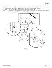
Wall Plate Wall Bumper Figure 15 Installation Manual Page - 15 - Use the wall bumper to the rods (Figure 15). Make any lateral shift adjustments and lock it by tightening the two (2) ¼"-20 Phillips screws found on the bottom of the wall carefully. NOTE: To remove the flat panel from the wall, simply back off the ¼"-20 screws using a Phillips screwdriver and lift the unit of the mounting brackets. PWM-F110 2. CAUTION: Do not over tighten the ¼"-20 screws to adjust your flat panel.
Wall Plate Wall Bumper Figure 15 Installation Manual Page - 15 - Use the wall bumper to the rods (Figure 15). Make any lateral shift adjustments and lock it by tightening the two (2) ¼"-20 Phillips screws found on the bottom of the wall carefully. NOTE: To remove the flat panel from the wall, simply back off the ¼"-20 screws using a Phillips screwdriver and lift the unit of the mounting brackets. PWM-F110 2. CAUTION: Do not over tighten the ¼"-20 screws to adjust your flat panel.