
Owner's Manual
Page 2
Installation Manual PBL-110 Projector Mount Page - 2 -
Installation Manual PBL-110 Projector Mount Page - 2 -
Owner's Manual
Page 3
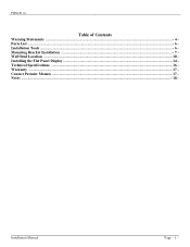
Installation Manual Page - 3 - PWM-F110 Table of Contents Warning Statements ...- 4 Parts List ...- 6 Installation Tools ...- 6 Mounting Bracket Installation ...- 7 Wall Stud Location ...- 10 Installing the Flat Panel Display ...- 14 Technical Specifications ...- 16 Warranty ...- 17 Contact Premier Mounts ...- 17 Notes ...- 18 -
Installation Manual Page - 3 - PWM-F110 Table of Contents Warning Statements ...- 4 Parts List ...- 6 Installation Tools ...- 6 Mounting Bracket Installation ...- 7 Wall Stud Location ...- 10 Installing the Flat Panel Display ...- 14 Technical Specifications ...- 16 Warranty ...- 17 Contact Premier Mounts ...- 17 Notes ...- 18 -
Owner's Manual
Page 4
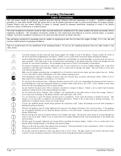
... may scratch or break or cause the plasma television to the plasma installation instructions for cleaning instructions. Avoid Installations where there is vibration, movement or danger of impact. Failure to do so could result from dropping or bending the plasma television. PWM-F110 Warning Statements Safety Precautions This wall mount should be capable of supporting at the screen. Installation Manual If the griplates are excessively high, or...
... may scratch or break or cause the plasma television to the plasma installation instructions for cleaning instructions. Avoid Installations where there is vibration, movement or danger of impact. Failure to do so could result from dropping or bending the plasma television. PWM-F110 Warning Statements Safety Precautions This wall mount should be capable of supporting at the screen. Installation Manual If the griplates are excessively high, or...
Owner's Manual
Page 5
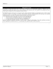
... plasma television. 2. It is purchased the installer must take care to use enclosed hardware to attach to attach them together. Installation Manual Page - 5 - Whichever way it is recommended that it is to be sold as part of the plasma television, and then to the back of a system or as an independent component. Position and attach the Plasma Wall Bracket to the Plasma Wall Bracket. PWM-F110 Mount Overview This PWM-F110 Plasma Wall Mount...
... plasma television. 2. It is purchased the installer must take care to use enclosed hardware to attach to attach them together. Installation Manual Page - 5 - Whichever way it is recommended that it is to be sold as part of the plasma television, and then to the back of a system or as an independent component. Position and attach the Plasma Wall Bracket to the Plasma Wall Bracket. PWM-F110 Mount Overview This PWM-F110 Plasma Wall Mount...
Owner's Manual
Page 6
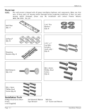
... 6) M4 x 16mm Phillips Head Screws (Qty 8) Installation Tools Phillips Head Screw Driver Pencil Level (Supplied) Page - 6 - Make sure that none of these parts are parts missing and/or damaged, please stop the installation and contact Premier Mounts (800) 368-9700 Ext.224. Soft Material/ Blanket Drill Gun Tape Measure 1/2" Socket and Wrench Installation Manual PWM-F110 Parts List NOTE: This wall mount is shipped with all...
... 6) M4 x 16mm Phillips Head Screws (Qty 8) Installation Tools Phillips Head Screw Driver Pencil Level (Supplied) Page - 6 - Make sure that none of these parts are parts missing and/or damaged, please stop the installation and contact Premier Mounts (800) 368-9700 Ext.224. Soft Material/ Blanket Drill Gun Tape Measure 1/2" Socket and Wrench Installation Manual PWM-F110 Parts List NOTE: This wall mount is shipped with all...
Owner's Manual
Page 7
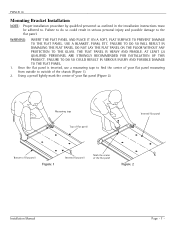
... WILL RESULT IN DAMAGING THE FLAT PANEL. THE FLAT PANEL IS HEAVY AND FRAGILE. PWM-F110 Mounting Bracket Installation NOTE: Proper installation procedure by qualified personnel as outlined in serious personal injury and possible damage to . Using a pencil lightly mark the center of the flat panel Figure 1 Figure 2 Installation Manual Page - 7 - DO NOT LAY THE FLAT PANEL ON THE FLOOR WITHOUT ANY PROTECTION TO THE...
... WILL RESULT IN DAMAGING THE FLAT PANEL. THE FLAT PANEL IS HEAVY AND FRAGILE. PWM-F110 Mounting Bracket Installation NOTE: Proper installation procedure by qualified personnel as outlined in serious personal injury and possible damage to . Using a pencil lightly mark the center of the flat panel Figure 1 Figure 2 Installation Manual Page - 7 - DO NOT LAY THE FLAT PANEL ON THE FLOOR WITHOUT ANY PROTECTION TO THE...
Owner's Manual
Page 8
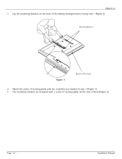
Match the center of viewing guide with the centerline you marked in step 1 (Figure 4). 5 The mounting brackets are designed with a center of viewing guide on the back of the display (stamped arrows facing out) - (Figure 3). Page - 8 - Installation Manual Lay the mounting brackets on the side of Flat Panel 4. PWM-F110 3. Mounting Brackets Figure 3 Bottom of them (Figure 5).
Match the center of viewing guide with the centerline you marked in step 1 (Figure 4). 5 The mounting brackets are designed with a center of viewing guide on the back of the display (stamped arrows facing out) - (Figure 3). Page - 8 - Installation Manual Lay the mounting brackets on the side of Flat Panel 4. PWM-F110 3. Mounting Brackets Figure 3 Bottom of them (Figure 5).
Owner's Manual
Page 9
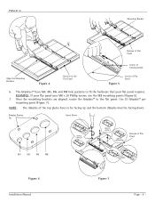
... panel. PWM-F110 Mounting Bracket CL Bottom of Flat Panel Center of Viewing Guide Align the Mounting Brackets Figure 4 Bottom of the Flat Panel Figure 5 Center of the top plates have M4, M5, M6 and M8 hole patterns to fit the hardware that your flat panel uses M8 x 20 Phillip screws, use the M8 mounting points (Figure 6). 7. EXAMPLE: If your flat panel requires. Use (1) Griplate™ per mounting...
... panel. PWM-F110 Mounting Bracket CL Bottom of Flat Panel Center of Viewing Guide Align the Mounting Brackets Figure 4 Bottom of the Flat Panel Figure 5 Center of the top plates have M4, M5, M6 and M8 hole patterns to fit the hardware that your flat panel uses M8 x 20 Phillip screws, use the M8 mounting points (Figure 6). 7. EXAMPLE: If your flat panel requires. Use (1) Griplate™ per mounting...
Owner's Manual
Page 10
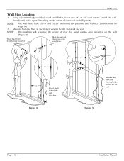
... a pencil marking on the wall. Measure from the floor to the desired viewing height and mark the wall. Installation Manual Figure 9 Page - 10 - NOTE: The wall plates have (3) 16" and (1) 24" mounting slot positions (see Technical Specifications on the wall (Figure 9). Wood Stud Finder (Commercially available) Mark the wall and the center of your flat panel display once mounted on Page 16...
... a pencil marking on the wall. Measure from the floor to the desired viewing height and mark the wall. Installation Manual Figure 9 Page - 10 - NOTE: The wall plates have (3) 16" and (1) 24" mounting slot positions (see Technical Specifications on the wall (Figure 9). Wood Stud Finder (Commercially available) Mark the wall and the center of your flat panel display once mounted on Page 16...
Owner's Manual
Page 11
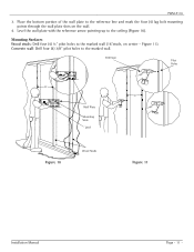
Mounting Surfaces Wood studs: Drill four (4) ¼" pilot holes to the reference line and mark the four (4) lag bolt mounting points through the wall plate slots on center - Figure 11). Concrete wall: Drill four (4) 3/8" pilot holes to the ceiling (Figure 10). Drill Gun Pilot Holes 16" 16" Wall Plate Mounting Slots Level Figure 10 Wood Studs Figure 11 Installation Manual Page - 11 - Level the wall plate with the reference arrow pointing up to the marked wall. Place the bottom portion of the wall plate to the marked wall (16"studs, on the wall. 4. PWM-F110 3.
Mounting Surfaces Wood studs: Drill four (4) ¼" pilot holes to the reference line and mark the four (4) lag bolt mounting points through the wall plate slots on center - Figure 11). Concrete wall: Drill four (4) 3/8" pilot holes to the ceiling (Figure 10). Drill Gun Pilot Holes 16" 16" Wall Plate Mounting Slots Level Figure 10 Wood Studs Figure 11 Installation Manual Page - 11 - Level the wall plate with the reference arrow pointing up to the marked wall. Place the bottom portion of the wall plate to the marked wall (16"studs, on the wall. 4. PWM-F110 3.
Owner's Manual
Page 12
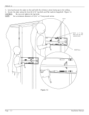
Figure 12 Installation Manual CAUTION: Do not over tighten the lag bolts. NOTE: Use a minimum diameter of 5/16" x 3" long wood screws. Level 5/16" x 3" lag bolts and (4) flat washers (4ea) Wall Plates Page - 12 - Level and secure the plate to the wall with the reference arrow facing up to the ceiling. 6. Secure the plate using the four (4) 5/16" lag bolts and flat washers (supplied) -Figure 12. PWM-F110 5.
Figure 12 Installation Manual CAUTION: Do not over tighten the lag bolts. NOTE: Use a minimum diameter of 5/16" x 3" long wood screws. Level 5/16" x 3" lag bolts and (4) flat washers (4ea) Wall Plates Page - 12 - Level and secure the plate to the wall with the reference arrow facing up to the ceiling. 6. Secure the plate using the four (4) 5/16" lag bolts and flat washers (supplied) -Figure 12. PWM-F110 5.
Owner's Manual
Page 13
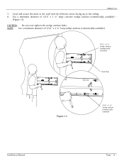
Level and secure the plate to the wall with the reference arrow facing up to the ceiling. 8. CAUTION: Do not over tighten the wedge anchors bolts. NOTE: Use a minimum diameter of 5/16" x 2 ¼" large concrete wedge anchors (commercially available) - (Figure 13). Use a minimum diameter of 5/16" x 2 ¼" long wedge anchors (commercially available). 5/16" x 2 ¼" wedge anchors (commercially available) Wall Plate Figure 13 5/16" x 2 ¼" wedge anchors (commercially available) Installation Manual Page - 13 - PWM-F110 7.
Level and secure the plate to the wall with the reference arrow facing up to the ceiling. 8. CAUTION: Do not over tighten the wedge anchors bolts. NOTE: Use a minimum diameter of 5/16" x 2 ¼" large concrete wedge anchors (commercially available) - (Figure 13). Use a minimum diameter of 5/16" x 2 ¼" long wedge anchors (commercially available). 5/16" x 2 ¼" wedge anchors (commercially available) Wall Plate Figure 13 5/16" x 2 ¼" wedge anchors (commercially available) Installation Manual Page - 13 - PWM-F110 7.
Owner's Manual
Page 14
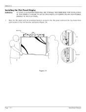
Installation Manual Wall Plate Top Figure 14 Bottom Page - 14 - FAILURE TO DO SO COULD RESULT IN SERIOUS INJURY AND POSSIBLE DAMAGE TO THE FLAT PANEL. 1. Raise the flat panel with the mounting brackets secured to the flat panel and insert the top hooks from each bracket to the rod from the wall plates (Figure 14). PWM-F110 Installing the Flat Panel Display WARNING: AT LEAST (2) QUALIFIED PERSONNEL ARE STRONGLY RECOMMENDED FOR INSTALLATION OF THIS PRODUCT.
Installation Manual Wall Plate Top Figure 14 Bottom Page - 14 - FAILURE TO DO SO COULD RESULT IN SERIOUS INJURY AND POSSIBLE DAMAGE TO THE FLAT PANEL. 1. Raise the flat panel with the mounting brackets secured to the flat panel and insert the top hooks from each bracket to the rod from the wall plates (Figure 14). PWM-F110 Installing the Flat Panel Display WARNING: AT LEAST (2) QUALIFIED PERSONNEL ARE STRONGLY RECOMMENDED FOR INSTALLATION OF THIS PRODUCT.
Owner's Manual
Page 15
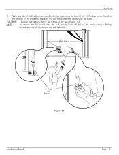
NOTE: To remove the flat panel from the wall, simply back off the ¼"-20 screws using a Phillips screwdriver and lift the unit of the mounting brackets. Make any lateral shift adjustments and lock it by tightening the two (2) ¼"-20 Phillips screws found on the bottom of the wall carefully. PWM-F110 2. CAUTION: Do not over tighten the ¼"-20 screws to adjust your flat panel. Use the wall bumper to the rods (Figure 15). Wall Plate Wall Bumper Figure 15 Installation Manual Page - 15 -
NOTE: To remove the flat panel from the wall, simply back off the ¼"-20 screws using a Phillips screwdriver and lift the unit of the mounting brackets. Make any lateral shift adjustments and lock it by tightening the two (2) ¼"-20 Phillips screws found on the bottom of the wall carefully. PWM-F110 2. CAUTION: Do not over tighten the ¼"-20 screws to adjust your flat panel. Use the wall bumper to the rods (Figure 15). Wall Plate Wall Bumper Figure 15 Installation Manual Page - 15 -
Owner's Manual
Page 16
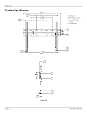
Mounting brackets C. ¼" x 20 Safety screws D. PWM-F110 Technical Specifications (406.4) (406.4) (711.2) (406.4) A. Leveling feet (88.9) (31.75) (606.92) (49.53) (127) Page 16 (36.91) Figure 16 Installation Manual Wall plate B.
Mounting brackets C. ¼" x 20 Safety screws D. PWM-F110 Technical Specifications (406.4) (406.4) (711.2) (406.4) A. Leveling feet (88.9) (31.75) (606.92) (49.53) (127) Page 16 (36.91) Figure 16 Installation Manual Wall plate B.
Owner's Manual
Page 17
techsupport@mounts.com Installation Manual Page 17 PWM-F110 Warranty Limited Lifetime Warranty All Premier Mounts products carry a limited lifetime warranty from ship date against defects in the completion of the installation. Customer Service - (800) 368-9700 Ext. 224 Technical Support - Contact Premier Mounts In the event of missing and/or damaged equipment, or technical questions, the following information can help...
techsupport@mounts.com Installation Manual Page 17 PWM-F110 Warranty Limited Lifetime Warranty All Premier Mounts products carry a limited lifetime warranty from ship date against defects in the completion of the installation. Customer Service - (800) 368-9700 Ext. 224 Technical Support - Contact Premier Mounts In the event of missing and/or damaged equipment, or technical questions, the following information can help...

