
Service Manual
Page 1
... No. ARP3355 SCHEMATIC DIAGRAM and PCB CONNECTION DIAGRAM CONTENTS 1. LTD. 253 Alexandra Road, #04-01, Singapore 159936 PIONEER CORPORATION 2006 T - Model Type Power Requirement Remarks PRO-507PU KUCXC AC120 V ¶ This service manual should be used together with the following manual(s): Model No. BLOCK DIAGRAM AND SCHEMATIC DIAGRAM 10 2.1 OVERALL WIRING DIAGRAM 10 2.2 HNM...
... No. ARP3355 SCHEMATIC DIAGRAM and PCB CONNECTION DIAGRAM CONTENTS 1. LTD. 253 Alexandra Road, #04-01, Singapore 159936 PIONEER CORPORATION 2006 T - Model Type Power Requirement Remarks PRO-507PU KUCXC AC120 V ¶ This service manual should be used together with the following manual(s): Model No. BLOCK DIAGRAM AND SCHEMATIC DIAGRAM 10 2.1 OVERALL WIRING DIAGRAM 10 2.2 HNM...
Service Manual
Page 2
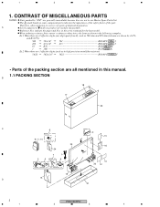
...all mentioned in the service manual for noise filter 23 16 24 7 1 2 5 Speed clamp x3 8 Bead band x3 10 20 12 19 15 D 21 2 PRO-507PU 1 2 3 4 indicate the pages and Nos. CONTRAST OF MISCELLANEOUS PARTS NOTES: Parts marked by J=5%, and K=10%). 560 56 x 101 561 RD1/4PU 5 6..., be sure to mark on some component parts indicates the importance of the safety factor of identical designation. A Screws adjacent to use parts of the part. Ex.1 When there are not in the following examples. Reference Nos. When ordering resistors, first convert resistance...
...all mentioned in the service manual for noise filter 23 16 24 7 1 2 5 Speed clamp x3 8 Bead band x3 10 20 12 19 15 D 21 2 PRO-507PU 1 2 3 4 indicate the pages and Nos. CONTRAST OF MISCELLANEOUS PARTS NOTES: Parts marked by J=5%, and K=10%). 560 56 x 101 561 RD1/4PU 5 6..., be sure to mark on some component parts indicates the importance of the safety factor of identical designation. A Screws adjacent to use parts of the part. Ex.1 When there are not in the following examples. Reference Nos. When ordering resistors, first convert resistance...
Service Manual
Page 4
...- 5 FRONT SECTION Front Case Assy (507PU) Pioneer Name Plate Elite Badge AMB2917 AAM1098 Not used AMB2918 Not used Note : For PCB ASSEMBLIES, Refer to " CONTRAST OF PCB ASSEMBLIES ". : The numbers in the remarks column correspond to the numbers on the " EXPLODED VIEWS ". 4 PRO-507PU 1 2 3 4 Chassis (507) Assy... 2..P. No. Chassis (507E) Assy AWU1212 AWU1148 Not used AWU1227 Not used AWU1187 P25 - 8 P25 - 10 P25 - 13 P25 - 16 P25 - 17 NSP ...
...- 5 FRONT SECTION Front Case Assy (507PU) Pioneer Name Plate Elite Badge AMB2917 AAM1098 Not used AMB2918 Not used Note : For PCB ASSEMBLIES, Refer to " CONTRAST OF PCB ASSEMBLIES ". : The numbers in the remarks column correspond to the numbers on the " EXPLODED VIEWS ". 4 PRO-507PU 1 2 3 4 Chassis (507) Assy... 2..P. No. Chassis (507E) Assy AWU1212 AWU1148 Not used AWU1227 Not used AWU1187 P25 - 8 P25 - 10 P25 - 13 P25 - 16 P25 - 17 NSP ...
Service Manual
Page 6
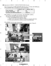
.../J J7601: ADX3483 yes no CN7802: KM200NA3L no yes Connection with MAIN ass'y Figure A Figure B When AWV2311-A /J is used in the product, order ADX3484 in addition, and connect it with MAIN ass'y, and only AWV2311-B /J is available as shown... A. 1. Solder it with MAIN ass'y When AWV2311-B /J is used in the product, replace the defective ass'y with a service parts ass'y as shown in interface with MAIN ass'y as shown in IC7803 C Figure A: AWV2311-A /J ADX3484 M17 D CN7802 Figure B: AWV2311-B /J 6 PRO-507PU 1 2 3 4 A /J AWV2311- Take off ADX3483 from the...
.../J J7601: ADX3483 yes no CN7802: KM200NA3L no yes Connection with MAIN ass'y Figure A Figure B When AWV2311-A /J is used in the product, order ADX3484 in addition, and connect it with MAIN ass'y, and only AWV2311-B /J is available as shown... A. 1. Solder it with MAIN ass'y When AWV2311-B /J is used in the product, replace the defective ass'y with a service parts ass'y as shown in interface with MAIN ass'y as shown in IC7803 C Figure A: AWV2311-A /J ADX3484 M17 D CN7802 Figure B: AWV2311-B /J 6 PRO-507PU 1 2 3 4 A /J AWV2311- Take off ADX3483 from the...
Service Manual
Page 7
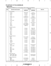
... [RGB SW BLOCK] C4945, C4946, C4947 R4901, R4902, R4904 Not used Not used CKSRYB105K10 RS1/16SS220J [MAIN UCOM BLOCK] R8454 R8470 R8469, R8453 RS1/16SS103J RS1/16SS103J Not used Not used Not used RS1/16SS103J Note: For Schematic Diagram and PCB Connection Diagram. ARP3355" Remarks PRO-507PU 5 6 7 8 A B C D 7 Refer to "Service Manual: Order No. 5 6 7 8 CONTRAST OF PCB ASSEMBLIES...
... [RGB SW BLOCK] C4945, C4946, C4947 R4901, R4902, R4904 Not used Not used CKSRYB105K10 RS1/16SS220J [MAIN UCOM BLOCK] R8454 R8470 R8469, R8453 RS1/16SS103J RS1/16SS103J Not used Not used Not used RS1/16SS103J Note: For Schematic Diagram and PCB Connection Diagram. ARP3355" Remarks PRO-507PU 5 6 7 8 A B C D 7 Refer to "Service Manual: Order No. 5 6 7 8 CONTRAST OF PCB ASSEMBLIES...
Service Manual
Page 8
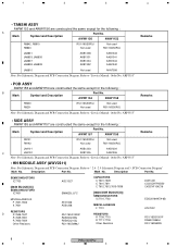
...Diagram. Description Part No. Refer to "Service Manual: Order No. AWW1154 AWW1158 Remarks R9200 R9201 RS1/16SS0R0J Not used Not used RS1/16SS0R0J Remarks JA9101 AKB1303 AKB1304 C JA9102 AKB1305 AKB1306 Note: For Schematic Diagram and PCB Connection Diagram. AWW1157... MISCELLANEOUS F 7701 RESISTORS R 7709,7710 R 7711-7718 Other Resistors DCH1201 CCSSCH7R0D50 CKSSYF104Z16 EDD2516AKTA-6B ATL7002 RS1/16SS1001F RAB4CQ560J RS1/16SS###J 8 PRO-507PU 1 2 3 4 ARP3355" • SIDE ASSY AWW1155 and AWW1157 are constructed the same except for the following : A Mark Symbol...
...Diagram. Description Part No. Refer to "Service Manual: Order No. AWW1154 AWW1158 Remarks R9200 R9201 RS1/16SS0R0J Not used Not used RS1/16SS0R0J Remarks JA9101 AKB1303 AKB1304 C JA9102 AKB1305 AKB1306 Note: For Schematic Diagram and PCB Connection Diagram. AWW1157... MISCELLANEOUS F 7701 RESISTORS R 7709,7710 R 7711-7718 Other Resistors DCH1201 CCSSCH7R0D50 CKSSYF104Z16 EDD2516AKTA-6B ATL7002 RS1/16SS1001F RAB4CQ560J RS1/16SS###J 8 PRO-507PU 1 2 3 4 ARP3355" • SIDE ASSY AWW1155 and AWW1157 are constructed the same except for the following : A Mark Symbol...
Service Manual
Page 13
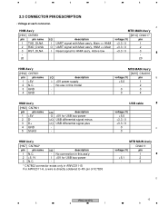
USB cable voltage (V) +5.0 +3.3 / 0 +3.3 / 0 0 C 0 HNM Ass'y [HN7] CN7802* pin pin name 1 N.C. 2 +5.1V 3 N.C. No use in this ass'y I /O USB differential signal plus - - No connection in AWV2311-B. I +5V power supply - HNM Ass'y A MTB MAIN Ass'y [HN1] CN7851 [M14] CN4017 pin pin ... PIN DESCRIPTION • Voltage at each connecter. For AWV2311-A, a wire is directly soldered to 4th pin of IC78.03 MTB MAIN Ass'y CN4011 voltage (V) pin - 1 +5.1 2 - 3 D PRO-507PU 13 5 6 7 8
USB cable voltage (V) +5.0 +3.3 / 0 +3.3 / 0 0 C 0 HNM Ass'y [HN7] CN7802* pin pin name 1 N.C. 2 +5.1V 3 N.C. No use in this ass'y I /O USB differential signal plus - - No connection in AWV2311-B. I +5V power supply - HNM Ass'y A MTB MAIN Ass'y [HN1] CN7851 [M14] CN4017 pin pin ... PIN DESCRIPTION • Voltage at each connecter. For AWV2311-A, a wire is directly soldered to 4th pin of IC78.03 MTB MAIN Ass'y CN4011 voltage (V) pin - 1 +5.1 2 - 3 D PRO-507PU 13 5 6 7 8
Service Manual
Page 30
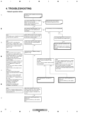
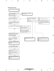
... 1 " in binary can be played? Subnet mask: 255.255.255.0 Replace the HNM ass'y with another IP Address: 192.168.201.1 one . 30 PRO-507PU 1 2 3 4 An example for the network address part designated by yourself. yes Jump and refer to set up. Note: When the DHCP server function is ... WMV. The failed contents may be out of the supported video format is not available in " Network yes Setup " menu to a used and correctly inserted into both network hub, a straight cable is properly set an appropriate IP address by the Subnet mask. ethernet terminal....
... 1 " in binary can be played? Subnet mask: 255.255.255.0 Replace the HNM ass'y with another IP Address: 192.168.201.1 one . 30 PRO-507PU 1 2 3 4 An example for the network address part designated by yourself. yes Jump and refer to set up. Note: When the DHCP server function is ... WMV. The failed contents may be out of the supported video format is not available in " Network yes Setup " menu to a used and correctly inserted into both network hub, a straight cable is properly set an appropriate IP address by the Subnet mask. ethernet terminal....
Service Manual
Page 31
...camera is attached to CN7802 or the 4th pin of the digital camera. One end is used as a USB device, try other contents. yes Is the USB device name or the directory in HNM ...ass'y. No Even if you use any other end is the main menu of "Fundamental No operation failure". yes If the contents...only. For example, most of 720p resolution are not supported by this . Replace the HNM ass'y with another one. D PRO-507PU 31 5 6 7 8 A Can "Home Media Gallery" on "HOME MENU" GUI be out of support. yes No Confirm...
...camera is attached to CN7802 or the 4th pin of the digital camera. One end is used as a USB device, try other contents. yes Is the USB device name or the directory in HNM ...ass'y. No Even if you use any other end is the main menu of "Fundamental No operation failure". yes If the contents...only. For example, most of 720p resolution are not supported by this . Replace the HNM ass'y with another one. D PRO-507PU 31 5 6 7 8 A Can "Home Media Gallery" on "HOME MENU" GUI be out of support. yes No Confirm...
Service Manual
Page 32
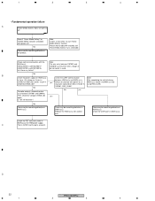
... HNM side and on , is Q4102 and the parts around it to start "Home Media Gallery" function. No There may be something defective in using RXD_DLNA. After completing the self-initializing, CN7901 of MAIN side? C That is HNM ass'y notice it . No To make analysis, remove the ...ass'y between CN7901 and CN4016 has only three wires, though 4pin connector is used. Replace the HNM ass'y with the MAIN ass'y. [HN1]CN7851[M14]CN4017 [HN2]CN7901[M15]CN4016 Isn't there any pulse signal observed on ? D 32 PRO-507PU 1 2 3 4 yes Almost 35 seconds after power-on 2nd pin in ...
... HNM side and on , is Q4102 and the parts around it to start "Home Media Gallery" function. No There may be something defective in using RXD_DLNA. After completing the self-initializing, CN7901 of MAIN side? C That is HNM ass'y notice it . No To make analysis, remove the ...ass'y between CN7901 and CN4016 has only three wires, though 4pin connector is used. Replace the HNM ass'y with the MAIN ass'y. [HN1]CN7851[M14]CN4017 [HN2]CN7901[M15]CN4016 Isn't there any pulse signal observed on ? D 32 PRO-507PU 1 2 3 4 yes Almost 35 seconds after power-on 2nd pin in ...


