Owner's Manual
Page 5
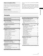
...the "Safety Precautions" and these "Operating Instructions" so you very much for purchasing this manual to the customer and explain to the customer how to deliver this PIONEER product. Before using your dealer install and set up the product. You will know how... Information 35 Cleaning 35 Troubleshooting 35 Specifications 38 Supplement 1 39 Supplement 2 41 Supplement 3 41 Supplement 4 42 Explanation of Terms 42 1 PRO-1000HDI / PRO-800HDI Contents Safety Precautions i Before Proceeding 2 How to Route Cables 17 Setting Up the System 18 Setup after Connection (INPUT1, 2 18...
...the "Safety Precautions" and these "Operating Instructions" so you very much for purchasing this manual to the customer and explain to the customer how to deliver this PIONEER product. Before using your dealer install and set up the product. You will know how... Information 35 Cleaning 35 Troubleshooting 35 Specifications 38 Supplement 1 39 Supplement 2 41 Supplement 3 41 Supplement 4 42 Explanation of Terms 42 1 PRO-1000HDI / PRO-800HDI Contents Safety Precautions i Before Proceeding 2 How to Route Cables 17 Setting Up the System 18 Setup after Connection (INPUT1, 2 18...
Owner's Manual
Page 6
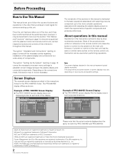
... trademarks of HDMI Licensing LLC. 2 PRO-1000HDI / PRO-800HDI The PRO-800HDI display differs as their respective buttons and controls will be referred to establish correct linkage between the plasma display and connected components. Before Proceeding How to Use This Manual This manual is set up to a wide variety... 8 covers all the parts have been received, it has been confirmed that would seem most logical for someone setting up this manual are written in both the PRO-1000HDI and PRO-800HDI. L E V E L B. Once the unit has been taken out of the box, and it may vary depending...
... trademarks of HDMI Licensing LLC. 2 PRO-1000HDI / PRO-800HDI The PRO-800HDI display differs as their respective buttons and controls will be referred to establish correct linkage between the plasma display and connected components. Before Proceeding How to Use This Manual This manual is set up to a wide variety... 8 covers all the parts have been received, it has been confirmed that would seem most logical for someone setting up this manual are written in both the PRO-1000HDI and PRO-800HDI. L E V E L B. Once the unit has been taken out of the box, and it may vary depending...
Owner's Manual
Page 7
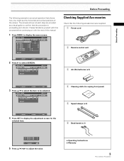
...Supplied Accessories Check that the procedure is an actual operation that shows how one might set the horizontal and vertical positions of this manual. 1 Press MENU to display the adjustment screen for the selected item. 4 Cleaning cloth (for wiping front panel) 5 Speed... +60 :0 :0 SET UP INPUT1 OPTION RE S ET SELECT SET ENTER MENU EXIT 2 Press 3 to adjust the value. ÷ Operating Instructions ÷ Warranty 3 PRO-1000HDI / PRO-800HDI R. E NHANCE V. POS I T I GHT . MAIN MENU PICTURE SCREEN POS I T I ON : 0 ADJUST MENU SET EXIT SET 5 Press 5/∞/2/3 ...
...Supplied Accessories Check that the procedure is an actual operation that shows how one might set the horizontal and vertical positions of this manual. 1 Press MENU to display the adjustment screen for the selected item. 4 Cleaning cloth (for wiping front panel) 5 Speed... +60 :0 :0 SET UP INPUT1 OPTION RE S ET SELECT SET ENTER MENU EXIT 2 Press 3 to adjust the value. ÷ Operating Instructions ÷ Warranty 3 PRO-1000HDI / PRO-800HDI R. E NHANCE V. POS I T I GHT . MAIN MENU PICTURE SCREEN POS I T I ON : 0 ADJUST MENU SET EXIT SET 5 Press 5/∞/2/3 ...
Owner's Manual
Page 12
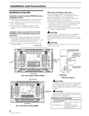
... bracket. ÷ For details concerning installation, please refer to the instruction manual provided with the stand or installation bracket. a hole Bolt 1/2 inches (12 mm) to 11/16 inches (18 mm) Center line Rear view diagram (PRO-1000HDI) Air vents (fan) a hole a hole Center line Bolt b hole... installation or mounting of this unit or the installation bracket by other than the PIONEER stand or installation bracket (sold separately) (For details, please consult the dealer where this unit was purchased. PIONEER will not be held responsible for both a holes and b holes. Also,...
... bracket. ÷ For details concerning installation, please refer to the instruction manual provided with the stand or installation bracket. a hole Bolt 1/2 inches (12 mm) to 11/16 inches (18 mm) Center line Rear view diagram (PRO-1000HDI) Air vents (fan) a hole a hole Center line Bolt b hole... installation or mounting of this unit or the installation bracket by other than the PIONEER stand or installation bracket (sold separately) (For details, please consult the dealer where this unit was purchased. PIONEER will not be held responsible for both a holes and b holes. Also,...
Owner's Manual
Page 15
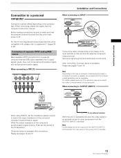
...connecting to INPUT1 INPUT1 OUTPUT ANALOG RGB (ANALOG RGB) Connect the cable corresponding to match the output impedance of your PC's instruction manual or consult the maker or nearest dealer of the connected computer's synchronization signal. On-screen setup is necessary. Note Depending on ... to OUTPUT (INPUT1) INPUT1 OUTPUT ANALOG RGB (ANALOG RGB) When using INPUT2, set this unit is off or in standby. 11 PRO-1000HDI / PRO-800HDI Before making connections, be sure to an external monitor or other component from the OUTPUT (INPUT1) terminal when the main power of...
...connecting to INPUT1 INPUT1 OUTPUT ANALOG RGB (ANALOG RGB) Connect the cable corresponding to match the output impedance of your PC's instruction manual or consult the maker or nearest dealer of the connected computer's synchronization signal. On-screen setup is necessary. Note Depending on ... to OUTPUT (INPUT1) INPUT1 OUTPUT ANALOG RGB (ANALOG RGB) When using INPUT2, set this unit is off or in standby. 11 PRO-1000HDI / PRO-800HDI Before making connections, be sure to an external monitor or other component from the OUTPUT (INPUT1) terminal when the main power of...

Owner's Manual
Page 18
... audio input terminals. Installation and Connections About DTV Set Top Box Connection To ensure proper connection, please carefully read the instruction manual supplied with a 2W+2W internal amplifier. Video signal type HDTV Video signal 1080i 720p Video signal format Component RGB Terminals where...unit and the corresponding terminals on this display is output from the • SPEAKER terminals • Stereo mini jack (L/R). 14 PRO-1000HDI / PRO-800HDI If speakers are as follows. Connecting the speakers This unit is equipped with the DTV set top box output signals that the...
... audio input terminals. Installation and Connections About DTV Set Top Box Connection To ensure proper connection, please carefully read the instruction manual supplied with a 2W+2W internal amplifier. Video signal type HDTV Video signal 1080i 720p Video signal format Component RGB Terminals where...unit and the corresponding terminals on this display is output from the • SPEAKER terminals • Stereo mini jack (L/R). 14 PRO-1000HDI / PRO-800HDI If speakers are as follows. Connecting the speakers This unit is equipped with the DTV set top box output signals that the...
Owner's Manual
Page 23
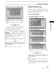
... screen. R. Notes ÷ Make this CLAMP POSITION setting for each input (INPUT1 and INPUT2). RGB COMPONENT The table below shows what settings are connecting. 19 PRO-1000HDI / PRO-800HDI MAIN MENU INPUT1 PICTURE SCREEN SET UP OPTION I NPUT L A BEL : I NPUT 1 POWE R MA NAGEME NT : OF F CL AMP P OS I T I ON...to select the input signal format. MAIN MENU PICTURE SCREEN CONT RAST BR I NG : VGA 4 Press SET to the instruction manual supplied with a whitish or greenish cast. Setting Up the System CLAMP POSITION setup Depending on the signal, analog RGB signals may...
... screen. R. Notes ÷ Make this CLAMP POSITION setting for each input (INPUT1 and INPUT2). RGB COMPONENT The table below shows what settings are connecting. 19 PRO-1000HDI / PRO-800HDI MAIN MENU INPUT1 PICTURE SCREEN SET UP OPTION I NPUT L A BEL : I NPUT 1 POWE R MA NAGEME NT : OF F CL AMP P OS I T I ON...to select the input signal format. MAIN MENU PICTURE SCREEN CONT RAST BR I NG : VGA 4 Press SET to the instruction manual supplied with a whitish or greenish cast. Setting Up the System CLAMP POSITION setup Depending on the signal, analog RGB signals may...

Owner's Manual
Page 24
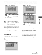
... Press 2/3 to select the desired VIDEO SIGNAL setting. MAIN MENU PICTURE SCREEN CONT RAST BR I O SEL ECT : AUT O 20 PRO-1000HDI / PRO-800HDI SELECT SET ENTER MENU EXIT Follow the procedure described below and make settings as shown: AUTO COLOR-1 COLOR-3 COLOR-2 AUTO: COLOR-1: ... Automatically identifies input video signals. CO LOR T I GHT . Accepts RGB signals. Each time SET is selected. 1 Press MENU to automatic or manual when inputting the digital signal. Accepts Y PB/CB PR/CR (4 : 2 : 2) signals. The menu screen appears. VIDEO SIGNAL This function ...
... Press 2/3 to select the desired VIDEO SIGNAL setting. MAIN MENU PICTURE SCREEN CONT RAST BR I O SEL ECT : AUT O 20 PRO-1000HDI / PRO-800HDI SELECT SET ENTER MENU EXIT Follow the procedure described below and make settings as shown: AUTO COLOR-1 COLOR-3 COLOR-2 AUTO: COLOR-1: ... Automatically identifies input video signals. CO LOR T I GHT . Accepts RGB signals. Each time SET is selected. 1 Press MENU to automatic or manual when inputting the digital signal. Accepts Y PB/CB PR/CR (4 : 2 : 2) signals. The menu screen appears. VIDEO SIGNAL This function ...
Owner's Manual
Page 25
... setting. CO LOR T I O SEL ECT : AUT O Setting Up the System 2 Press 2/3 to select AUDIO SELECT. Setting Up the System 3 Press 5/∞ to automatic or manual when inputting the digital signal. MAIN MENU INPUT5 PICTURE SCREEN SET UP OPTION I NPUT L ABEL : I NPUT 5 AUT O P OWER OF F : OF F COL OR T EMP...The unit has been factory set up. In this event, select TYPE-1 or TYPE-2 manually in accordance with someinput signals. SELECT SET ENTER MENU EXIT 21 PRO-1000HDI / PRO-800HDI Each time SET is selected, automatic switching may occur properly with the actual signal ...
... setting. CO LOR T I O SEL ECT : AUT O Setting Up the System 2 Press 2/3 to select AUDIO SELECT. Setting Up the System 3 Press 5/∞ to automatic or manual when inputting the digital signal. MAIN MENU INPUT5 PICTURE SCREEN SET UP OPTION I NPUT L ABEL : I NPUT 5 AUT O P OWER OF F : OF F COL OR T EMP...The unit has been factory set up. In this event, select TYPE-1 or TYPE-2 manually in accordance with someinput signals. SELECT SET ENTER MENU EXIT 21 PRO-1000HDI / PRO-800HDI Each time SET is selected, automatic switching may occur properly with the actual signal ...

Owner's Manual
Page 32
.... L E V E L B. E NHANCE V. In this adjustment individually for each input function (INPUT1 or INPUT2), and each input and signals. Manual Adjustment of Screen Position and Clock Note Make these adjustments for low- V.POSITION Adjust the picture's position upward or downward. R. L EVEL H. PHASE ...I ON : CL OCK / PHASE : SET UP 0/ 0 0/ 0 RE S ET INPUT1 OPTION SELECT SET ENTER MENU EXIT 28 PRO-1000HDI / PRO-800HDI Display Panel Adjustments Adjusting the Image Position and Clock (Automatic Adjustment) Pressing AUTO SET UP on either the main unit operating panel or ...
.... L E V E L B. E NHANCE V. In this adjustment individually for each input function (INPUT1 or INPUT2), and each input and signals. Manual Adjustment of Screen Position and Clock Note Make these adjustments for low- V.POSITION Adjust the picture's position upward or downward. R. L EVEL H. PHASE ...I ON : CL OCK / PHASE : SET UP 0/ 0 0/ 0 RE S ET INPUT1 OPTION SELECT SET ENTER MENU EXIT 28 PRO-1000HDI / PRO-800HDI Display Panel Adjustments Adjusting the Image Position and Clock (Automatic Adjustment) Pressing AUTO SET UP on either the main unit operating panel or ...


