Operating Instructions
Page 4
... ...24 CLEANING ...25 SPECIFICATIONS ...26 17 En Please read through these operating instructions so you will know how to Use Cable Clip Alignment of the Pioneer plasma display, consult the Plasma Display Operating Instructions. It cannot be used with Pioneer Plasma Display models PDP-504CMX/ PDP-504CMX-S/PDP-503CMX and PDP-50MXE1/ PDP-50MXE1-S/PDP-503MXE.
... ...24 CLEANING ...25 SPECIFICATIONS ...26 17 En Please read through these operating instructions so you will know how to Use Cable Clip Alignment of the Pioneer plasma display, consult the Plasma Display Operating Instructions. It cannot be used with Pioneer Plasma Display models PDP-504CMX/ PDP-504CMX-S/PDP-503CMX and PDP-50MXE1/ PDP-50MXE1-S/PDP-503MXE.
Operating Instructions
Page 7
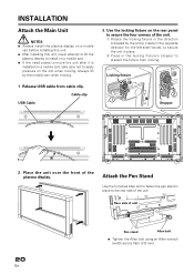
...the rear side of the unit. INSTALLATION Attach the Main Unit NOTES: ÷ Always install the plasma display on a mobile cart before installing this unit. ÷ After installing this unit, never attempt to lift the plasma display to install on a mobile cart. ÷ If the need arises to move the unit after ...it is installed on a mobile cart, take care not to apply pressure on the rear panel to secure the four corners of the unit. 1 Rotate the...
...the rear side of the unit. INSTALLATION Attach the Main Unit NOTES: ÷ Always install the plasma display on a mobile cart before installing this unit. ÷ After installing this unit, never attempt to lift the plasma display to install on a mobile cart. ÷ If the need arises to move the unit after ...it is installed on a mobile cart, take care not to apply pressure on the rear panel to secure the four corners of the unit. 1 Rotate the...
Operating Instructions
Page 8
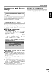
Look at the plasma display's Operating Instruction items for the driver software (provided with this unit). Set "SIGNAL FORMAT". Example of menu displayed on the PDP504CMX/PDP-50MXE1 MENU INPUT1 PICTURE SCREEN SETUP OPTION POWER MANAGEMENT CLAMP POSITION SIGNAL FORMAT : OFF : AUTO : XGA 7 ... With the screen image turned on, select MENU = SETUP = SIGNAL FORMAT = SET, and change the XGA setting to plasma display and computer. Consult the plasma display's Operating Instructions for details on how to confirm these settings. ÷ Confirm that "MASK CONTROL" and "ORBITER" are set...
Look at the plasma display's Operating Instruction items for the driver software (provided with this unit). Set "SIGNAL FORMAT". Example of menu displayed on the PDP504CMX/PDP-50MXE1 MENU INPUT1 PICTURE SCREEN SETUP OPTION POWER MANAGEMENT CLAMP POSITION SIGNAL FORMAT : OFF : AUTO : XGA 7 ... With the screen image turned on, select MENU = SETUP = SIGNAL FORMAT = SET, and change the XGA setting to plasma display and computer. Consult the plasma display's Operating Instructions for details on how to confirm these settings. ÷ Confirm that "MASK CONTROL" and "ORBITER" are set...
Operating Instructions
Page 11
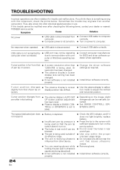
...; Turn on the image, slight divergences can be rectified even after initial setting. ÷ The plasma display's AUTO SET UP screen position adjustment has been reset. ÷ Plasma display's [MASK CONTROL] or [ORBITER] is not recognized by computer when connected. ÷ USB port...position. Cursor position diverges from pen after checking the following items, contact your dealer or nearest PIONEER service center. Or resolution has been changed. ÷ The plasma display's screen display size setting has been changed. ÷ Driver software is disconnected. ÷ Connect USB cable...
...; Turn on the image, slight divergences can be rectified even after initial setting. ÷ The plasma display's AUTO SET UP screen position adjustment has been reset. ÷ Plasma display's [MASK CONTROL] or [ORBITER] is not recognized by computer when connected. ÷ USB port...position. Cursor position diverges from pen after checking the following items, contact your dealer or nearest PIONEER service center. Or resolution has been changed. ÷ The plasma display's screen display size setting has been changed. ÷ Driver software is disconnected. ÷ Connect USB cable...
Operating Instructions
Page 13
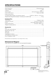
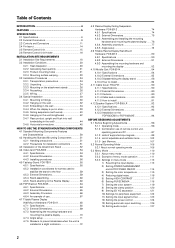
...; 2004 Pioneer Corporation. All rights reserved. SPECIFICATIONS Scanning system Infrared scanning Power indicator ...LED Interface ...USB 1.1 Power supply self-powered from USB port Power consumption Maximum 2.5W External dimensions (including plasma display, excluding pen stand 1,258 (W) x 758 (H) x 115 (D) mm Weight (excluding plasma display, including ... Specifications and appearance may change without notice. Dimensional Diagram (View when this unit installed on the PDP-504CMX/PDP-50MXE1) 1258 115 92 74 (excluding the bolt head) 758 56 Unit: mm 26 En 58 220 120 Published by...
...; 2004 Pioneer Corporation. All rights reserved. SPECIFICATIONS Scanning system Infrared scanning Power indicator ...LED Interface ...USB 1.1 Power supply self-powered from USB port Power consumption Maximum 2.5W External dimensions (including plasma display, excluding pen stand 1,258 (W) x 758 (H) x 115 (D) mm Weight (excluding plasma display, including ... Specifications and appearance may change without notice. Dimensional Diagram (View when this unit installed on the PDP-504CMX/PDP-50MXE1) 1258 115 92 74 (excluding the bolt head) 758 56 Unit: mm 26 En 58 220 120 Published by...
Technical Manual
Page 1
...safety information. TECHNICAL MANUAL (Ver. 1.0) PLASMA DISPLAY MONITOR: PDP-503CMX/PDP-503MXE VIDEO CARD: PDA-5002 TABLE TOP STAND: PDK-TS01 PDP BRACKET: PDK-5005 PLASMA DISPLAY WALL-MOUNT HARDWARE: PDK-5011 PLASMA DISPLAY CEILING SUSPENSION HARDWARE: PDK-5012 PLASMA DISPLAY WALL-MOUNT HARDWARE: PDK-5013 MOBILE CART... and adjusted as described in this product, or resulting from modifications made to qualified personnel, or consult the nearest PIONEER dealer for assistance. ÷ We accept no responsibility for installation, preparation, and handling of construction, materials used,...
...safety information. TECHNICAL MANUAL (Ver. 1.0) PLASMA DISPLAY MONITOR: PDP-503CMX/PDP-503MXE VIDEO CARD: PDA-5002 TABLE TOP STAND: PDK-TS01 PDP BRACKET: PDK-5005 PLASMA DISPLAY WALL-MOUNT HARDWARE: PDK-5011 PLASMA DISPLAY CEILING SUSPENSION HARDWARE: PDK-5012 PLASMA DISPLAY WALL-MOUNT HARDWARE: PDK-5013 MOBILE CART... and adjusted as described in this product, or resulting from modifications made to qualified personnel, or consult the nearest PIONEER dealer for assistance. ÷ We accept no responsibility for installation, preparation, and handling of construction, materials used,...
Technical Manual
Page 2
...TO USE THE STANDARD MOUNTING COMPONENTS 4.1 Standard Mounting Components Features and Characteristics 50 4.2 Handling the Standard Mounting Components 51 4.2.1 Handling precautions 51 4.2.2 ... to the Plasma Display 60 4.6 PDP Bracket: PDK-5005 64 4.6.1 Specifications 64 4.6.2 External Dimensions 65 4.6.3 Assembly Procedure 66 4.6.4 An example of use 67 4.7 Tiltable Plasma Display Wall-Mount ...on the PDP-503CMX or PDP-503MXE 94 BEFORE BEGINNING ADJUSTMENTS 5.1 Before Beginning Adjustments 96 5.1.1 Operating mode 96 5.1.2 Combination use of remote control unit, operating panel and ...
...TO USE THE STANDARD MOUNTING COMPONENTS 4.1 Standard Mounting Components Features and Characteristics 50 4.2 Handling the Standard Mounting Components 51 4.2.1 Handling precautions 51 4.2.2 ... to the Plasma Display 60 4.6 PDP Bracket: PDK-5005 64 4.6.1 Specifications 64 4.6.2 External Dimensions 65 4.6.3 Assembly Procedure 66 4.6.4 An example of use 67 4.7 Tiltable Plasma Display Wall-Mount ...on the PDP-503CMX or PDP-503MXE 94 BEFORE BEGINNING ADJUSTMENTS 5.1 Before Beginning Adjustments 96 5.1.1 Operating mode 96 5.1.2 Combination use of remote control unit, operating panel and ...
Technical Manual
Page 5
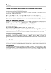
... . The thinner, lighter design, coupled to a minimum, producing clear, high-contrast images even in a lighted room. Features Features and Functions of the PDP-503CMX/PDP-503MXE Plasma Display Introduces newly developed 50" XGA Wide Plasma Panel The new high-precision XGA 50" wide plasma panel pushes the envelope of previous high-luminance panels, producing brighter, clearer images with color-bar signal input). 5
... . The thinner, lighter design, coupled to a minimum, producing clear, high-contrast images even in a lighted room. Features Features and Functions of the PDP-503CMX/PDP-503MXE Plasma Display Introduces newly developed 50" XGA Wide Plasma Panel The new high-precision XGA 50" wide plasma panel pushes the envelope of previous high-luminance panels, producing brighter, clearer images with color-bar signal input). 5
Technical Manual
Page 6
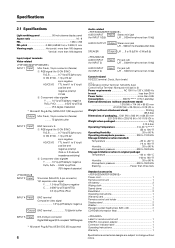
Specifications 2.1 Specifications Light-emitting panel 50-inch plasma display panel Aspect ratio 16 : 9 PEL 1280 × 768 PEL pitch 0.858 (H•RGB trio) × 0.808 (V) mm Viewing angle Horizontal: more than 160 ... three tiers Standard accessories Power cord 1 Remote control unit 1 AA battery 2 Wiping cloth 1 Speed clamp 2 Bead Band 2 Operating instructions 1 Warranty card 1 Remote control unit holder 1 Display stand 2 Washer 2 Hexagon socket head screw (M8 x 40 2 CD-ROM (information files 1 Label for G ON SYNC) R,G,B 0.7 Vp-p/75 Ω/no sync G ON SYNC ...
Specifications 2.1 Specifications Light-emitting panel 50-inch plasma display panel Aspect ratio 16 : 9 PEL 1280 × 768 PEL pitch 0.858 (H•RGB trio) × 0.808 (V) mm Viewing angle Horizontal: more than 160 ... three tiers Standard accessories Power cord 1 Remote control unit 1 AA battery 2 Wiping cloth 1 Speed clamp 2 Bead Band 2 Operating instructions 1 Warranty card 1 Remote control unit holder 1 Display stand 2 Washer 2 Hexagon socket head screw (M8 x 40 2 CD-ROM (information files 1 Label for G ON SYNC) R,G,B 0.7 Vp-p/75 Ω/no sync G ON SYNC ...

Technical Manual
Page 12
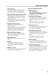
... INPUT OUTPUT (INPUT1/2) 56 7 89 0 Plasma Display Section 1 SPEAKER (R) terminal For connection of 5 including the set that bear the Î mark. And it is 8 -16 Ω. 2 CONTROL IN/OUT (monaural mini jacks) For connection of PIONEER components that the signal is at least TTL ... output is that the sink level of the source used is initially input to an external monitor or other multi-projection. Controls and Connectors Connection Panel AC INLET OFF ON - = INPUT5 DIGITAL RGB AUDIO R INPUT3 S-VIDEO L AUDIO R INPUT4 VIDEO L OUTPUT ! @ # $ %^ 8Ω ~16Ω ...
... INPUT OUTPUT (INPUT1/2) 56 7 89 0 Plasma Display Section 1 SPEAKER (R) terminal For connection of 5 including the set that bear the Î mark. And it is 8 -16 Ω. 2 CONTROL IN/OUT (monaural mini jacks) For connection of PIONEER components that the signal is at least TTL ... output is that the sink level of the source used is initially input to an external monitor or other multi-projection. Controls and Connectors Connection Panel AC INLET OFF ON - = INPUT5 DIGITAL RGB AUDIO R INPUT3 S-VIDEO L AUDIO R INPUT4 VIDEO L OUTPUT ! @ # $ %^ 8Ω ~16Ω ...
Technical Manual
Page 13
... Card Section # ! Connect these jacks to the audio output connectors of components connected to connect a computer. Note: This unit does not support the display of copyguard-protected video signals. @ AUDIO INPUT3 (RCA Pin jacks) Use to an AV amplifier or similar component. - Note: The left audio channel...the power cable to this connector and the other component. Connect this jack to the audio output connector of the device connected to the plasma display's INPUT1 or INPUT2, or to the audio output connector of the device connected to the video card's INPUT5#. 0 AUDIO OUTPUT (Stereo ...
... Card Section # ! Connect these jacks to the audio output connectors of components connected to connect a computer. Note: This unit does not support the display of copyguard-protected video signals. @ AUDIO INPUT3 (RCA Pin jacks) Use to an AV amplifier or similar component. - Note: The left audio channel...the power cable to this connector and the other component. Connect this jack to the audio output connector of the device connected to the plasma display's INPUT1 or INPUT2, or to the audio output connector of the device connected to the video card's INPUT5#. 0 AUDIO OUTPUT (Stereo ...
Technical Manual
Page 18
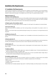
...Install the unit so that the load is not suited for open-air use. Avoid locations subject to direct sunlight. 18 In installing the display, avoid sites exposed to high vibration or severe impacts. 7) Lighting conditions • Consider existing lighting and sunlight angles when creating the ... trouble. Installation Site Requirements 3.1 Installation Site Requirements If the site requires modifications or special preparations for installation of the plasma display or its mounting hardware, obtain permission in mind that extreme intensity settings can reduce the visibility and quality of the...
...Install the unit so that the load is not suited for open-air use. Avoid locations subject to direct sunlight. 18 In installing the display, avoid sites exposed to high vibration or severe impacts. 7) Lighting conditions • Consider existing lighting and sunlight angles when creating the ... trouble. Installation Site Requirements 3.1 Installation Site Requirements If the site requires modifications or special preparations for installation of the plasma display or its mounting hardware, obtain permission in mind that extreme intensity settings can reduce the visibility and quality of the...

Technical Manual
Page 19
...; This unit functions properly when powered at ±10 % of leakage breakers and form branches in each country flows from the display or contact Pioneer authorized dealer for an hour or so. Connect the power cord by inserting it has a non-operating current that the cord is...assistance. Beware of the following occurs, contact an electrician to inspect the power. • Significant voltage drop between the circuit panel and the plasma display • Significant changes in order to prevent electric shock caused by standards in the wiring system. 12) Effective remote control distance...
...; This unit functions properly when powered at ±10 % of leakage breakers and form branches in each country flows from the display or contact Pioneer authorized dealer for an hour or so. Connect the power cord by inserting it has a non-operating current that the cord is...assistance. Beware of the following occurs, contact an electrician to inspect the power. • Significant voltage drop between the circuit panel and the plasma display • Significant changes in order to prevent electric shock caused by standards in the wiring system. 12) Effective remote control distance...
Technical Manual
Page 23
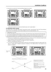
... extend string of intersection. Distortion is expressed by Pioneer, perform the following to confirm that the display is found to prevent pinching the power cord or signal cables.) 3.2.4 Mounting surface warping The display section incorporates glass. Clearance between the strings at... the other than 1mm. 1 Referring to 3mm. Any value of L greater than 0 indicates the presence of string segment A-B. A A Mount bolt holes Plasma Display Mount Surface (Mount Brackets) A String F E String C D Magnified view of section A Point E is negligible. D. Point F is the center point...
... extend string of intersection. Distortion is expressed by Pioneer, perform the following to confirm that the display is found to prevent pinching the power cord or signal cables.) 3.2.4 Mounting surface warping The display section incorporates glass. Clearance between the strings at... the other than 1mm. 1 Referring to 3mm. Any value of L greater than 0 indicates the presence of string segment A-B. A A Mount bolt holes Plasma Display Mount Surface (Mount Brackets) A String F E String C D Magnified view of section A Point E is negligible. D. Point F is the center point...

Technical Manual
Page 24
... same way as when they were originally shipped. Failure to prevent it from being dameged. 3.3.2 Unpacking The original packing material can damage the display. 1) Packing specifications: 1341 (W) × 846 (H) × 424 (D), 51 kg 1 Ref. Terms 1 Upper face of the carton...4 For transportation or storage, observe the warnings and instructions on the upper face of the carton. 5 Plasma display is important to sofely ship the Plasma Display. Installation Procedures 3.3 Installation Procedures 3.3.1 Transportation precautions 1 Any transportation of the unopened unit in its packing ...
... same way as when they were originally shipped. Failure to prevent it from being dameged. 3.3.2 Unpacking The original packing material can damage the display. 1) Packing specifications: 1341 (W) × 846 (H) × 424 (D), 51 kg 1 Ref. Terms 1 Upper face of the carton...4 For transportation or storage, observe the warnings and instructions on the upper face of the carton. 5 Plasma display is important to sofely ship the Plasma Display. Installation Procedures 3.3 Installation Procedures 3.3.1 Transportation precautions 1 Any transportation of the unopened unit in its packing ...

