
Technical Manual
Page 3
... PDA-5002 153 23) Simple checking of internal temperature .. 154 24) Checking the accumulated ON time ......... 155 5.4.4 PICTURE and WHITE BALANCE adjustment values memory area tables 156 5.4.5 SCREEN adjustment values area tables .......... 158 5.5 RS-232C Adjustment Mode 160 5.5.1 About the RS-232C adjustment mode 160 5.5.2 Interface 161 5.5.3 ID assignment 163 5.5.4 List of...
... PDA-5002 153 23) Simple checking of internal temperature .. 154 24) Checking the accumulated ON time ......... 155 5.4.4 PICTURE and WHITE BALANCE adjustment values memory area tables 156 5.4.5 SCREEN adjustment values area tables .......... 158 5.5 RS-232C Adjustment Mode 160 5.5.1 About the RS-232C adjustment mode 160 5.5.2 Interface 161 5.5.3 ID assignment 163 5.5.4 List of...

Technical Manual
Page 11
Note When optional speakers have been connected, the operation panel on the unit. 0 SCREEN SIZE button Press to optimum values. 11 2.3 Controls and Connectors Main unit Main unit 3 Controls and Connectors Operation panel on the main unit 4 5 6 7 8 9 0 - 1 2 Main unit 1 Display stand 2 Remote control sensor ... on-screen menu. 8 ADJUST (5/∞/3/2) buttons Use to navigate menu screens and to adjust various settings on the unit. Operation panel on the main unit 4 STANDBY/ON button Press to indicate error messages. The flashing pattern is operating. AUTO SET UP button ...
Note When optional speakers have been connected, the operation panel on the unit. 0 SCREEN SIZE button Press to optimum values. 11 2.3 Controls and Connectors Main unit Main unit 3 Controls and Connectors Operation panel on the main unit 4 5 6 7 8 9 0 - 1 2 Main unit 1 Display stand 2 Remote control sensor ... on-screen menu. 8 ADJUST (5/∞/3/2) buttons Use to navigate menu screens and to adjust various settings on the unit. Operation panel on the main unit 4 STANDBY/ON button Press to indicate error messages. The flashing pattern is operating. AUTO SET UP button ...
Technical Manual
Page 15
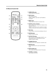
... Press to mute the volume. 7 AUTO SET UP button When entering a computer signal to INPUT 1 or 2, automatically sets the POSITION and CLOCK/ PHASE to optimum values. 8 STANDBY/ON button Press to put the unit in operation or standby mode. 9 DISPLAY button Press to view the unit's current input and setup mode...
... Press to mute the volume. 7 AUTO SET UP button When entering a computer signal to INPUT 1 or 2, automatically sets the POSITION and CLOCK/ PHASE to optimum values. 8 STANDBY/ON button Press to put the unit in operation or standby mode. 9 DISPLAY button Press to view the unit's current input and setup mode...

Technical Manual
Page 19
... in a grounded electrical outlet and securely attach the ground wire. • A leakage current within a value stipulated by standards in each country flows from the display or contact Pioneer authorized dealer for assistance. 11) Power requirements • This unit functions properly when powered at least two...radiation. If any of the following occurs, contact an electrician to inspect the power. • Significant voltage drop between the circuit panel and the plasma display • Significant changes in voltage when switching the unit power on or off for 400 W ≠ 400 VA of ...
... in a grounded electrical outlet and securely attach the ground wire. • A leakage current within a value stipulated by standards in each country flows from the display or contact Pioneer authorized dealer for assistance. 11) Power requirements • This unit functions properly when powered at least two...radiation. If any of the following occurs, contact an electrician to inspect the power. • Significant voltage drop between the circuit panel and the plasma display • Significant changes in voltage when switching the unit power on or off for 400 W ≠ 400 VA of ...
Technical Manual
Page 23
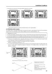
...point of string segment A-B. Before mounting the product, using hardware other bolt mount openings and repeat the measurements. If the measured value in the display may have a warp of intersection. Point F is negligible. Distortion is the center point of string segment C-D. ... may be put under excessive stress. A A Mount bolt holes Plasma Display Mount Surface (Mount Brackets) A String F E String C D Magnified view of section A Point E is expressed by Pioneer, perform the following to 3mm. Any value of L greater than that the warp of the mount surface is...
...point of string segment A-B. Before mounting the product, using hardware other bolt mount openings and repeat the measurements. If the measured value in the display may have a warp of intersection. Point F is negligible. Distortion is the center point of string segment C-D. ... may be put under excessive stress. A A Mount bolt holes Plasma Display Mount Surface (Mount Brackets) A String F E String C D Magnified view of section A Point E is expressed by Pioneer, perform the following to 3mm. Any value of L greater than that the warp of the mount surface is...