Operating Instructions
Page 99
...companies do this, please contact your nearest Pioneer subsidiary in your country or the regional headquarters, listed below , information is available in Japan / Imprimé au Japon < Professional PDP > AFTER-SALES SUPPORT FOR PIONEER PRODUCTS Please contact the dealer or the ...distributor from where you are situated) AMERICA PIONEER ELECTRONICS (USA) INC After-Sales Service Customer Support Division PO BOX 1760 Long Beach, CA. 90801-1760, ...
...companies do this, please contact your nearest Pioneer subsidiary in your country or the regional headquarters, listed below , information is available in Japan / Imprimé au Japon < Professional PDP > AFTER-SALES SUPPORT FOR PIONEER PRODUCTS Please contact the dealer or the ...distributor from where you are situated) AMERICA PIONEER ELECTRONICS (USA) INC After-Sales Service Customer Support Division PO BOX 1760 Long Beach, CA. 90801-1760, ...
Technical Manual
Page 2
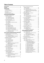
... USE THE STANDARD MOUNTING COMPONENTS 4.1 Standard Mounting Components Features and Characteristics 50 4.2 Handling the Standard Mounting Components 51 4.2.1 Handling precautions 51 4.2.2 ...and Installing the mounting hardware and mounting the plasma display ...... 76 4.8.4 Assembly procedure 77 4.8.5 Angle setup 78 4.9 Tiltable Plasma Display Wall-Mount Hardware: PDK-5013 80...PDP-503CMX or PDP-503MXE 94 BEFORE BEGINNING ADJUSTMENTS 5.1 Before Beginning Adjustments 96 5.1.1 Operating mode 96 5.1.2 Combination use of remote control unit, operating panel and PC 97 5.1.3 Lists of supported...
... USE THE STANDARD MOUNTING COMPONENTS 4.1 Standard Mounting Components Features and Characteristics 50 4.2 Handling the Standard Mounting Components 51 4.2.1 Handling precautions 51 4.2.2 ...and Installing the mounting hardware and mounting the plasma display ...... 76 4.8.4 Assembly procedure 77 4.8.5 Angle setup 78 4.9 Tiltable Plasma Display Wall-Mount Hardware: PDK-5013 80...PDP-503CMX or PDP-503MXE 94 BEFORE BEGINNING ADJUSTMENTS 5.1 Before Beginning Adjustments 96 5.1.1 Operating mode 96 5.1.2 Combination use of remote control unit, operating panel and PC 97 5.1.3 Lists of supported...
Technical Manual
Page 5
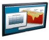
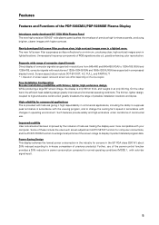
...PDP-503CMX/PDP-503MXE Plasma Display Introduces newly developed 50" XGA Wide Plasma Panel The new high-precision XGA 50" wide plasma panel pushes the envelope of 1280x1024 (SXGA) and 1600x1200 (UXGA) are also cut, greatly enhancing color reproduction. computer signals with resolutions of previous high-luminance panels...convenience has been improved by the inclusion of the power-control function provides a 20% reduction in operating environment. Supports wide range of computer signal formats Direct display of possible installation locations and styles. The thinner, lighter design, ...
...PDP-503CMX/PDP-503MXE Plasma Display Introduces newly developed 50" XGA Wide Plasma Panel The new high-precision XGA 50" wide plasma panel pushes the envelope of 1280x1024 (SXGA) and 1600x1200 (UXGA) are also cut, greatly enhancing color reproduction. computer signals with resolutions of previous high-luminance panels...convenience has been improved by the inclusion of the power-control function provides a 20% reduction in operating environment. Supports wide range of computer signal formats Direct display of possible installation locations and styles. The thinner, lighter design, ...
Technical Manual
Page 6
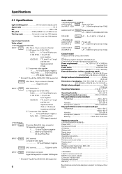
...with buffer INPUT 5 Input DVI-D 24-pin connector Digital RGB signal (DVI compliant TMDS signal) * Microsoft Plug & Play (VESA DDC 2B) supported 6 Audio-related AUDIO INPUT Input Stereo mini jack (for INPUT 1/2/5) L/R ... 500mVrms/more than 10 kΩ AUDIO OUTPUT Output Stereo mini ...°C (-40 to 140 °F) Humidity 20 to 90 % Atmospheric pressure 600 to change without notice. Specifications 2.1 Specifications Light-emitting panel 50-inch plasma display panel Aspect ratio 16 : 9 PEL 1280 × 768 PEL pitch 0.858 (H•RGB trio) × 0.808 (V) mm Viewing angle ...
...with buffer INPUT 5 Input DVI-D 24-pin connector Digital RGB signal (DVI compliant TMDS signal) * Microsoft Plug & Play (VESA DDC 2B) supported 6 Audio-related AUDIO INPUT Input Stereo mini jack (for INPUT 1/2/5) L/R ... 500mVrms/more than 10 kΩ AUDIO OUTPUT Output Stereo mini ...°C (-40 to 140 °F) Humidity 20 to 90 % Atmospheric pressure 600 to change without notice. Specifications 2.1 Specifications Light-emitting panel 50-inch plasma display panel Aspect ratio 16 : 9 PEL 1280 × 768 PEL pitch 0.858 (H•RGB trio) × 0.808 (V) mm Viewing angle ...

Technical Manual
Page 7
...2) (NOTE 3) The display is preset at the factory to Installation Site Requirements.) INPUT Response Signals INPUT 1, 2 & Video signals supported # Vertical Horizontal Frequency Frequency Fv (Hz) Fh (kHz) 15.625 50 28.1 31.25 15.734 31.5 60 33.75 45.0 67.5 Signal Format Component RGB Component RGB Component RGB Component...575p) SDTV 520i(480i) SDTV 525p(480p) SDTV 1125i(1035i, 1080i) HDTV High vision video signal 750p(720p) HDTV 1125p(1080p) HDTV & PC signals supported Resolution (Dot x Line) 640 x 400 640 x 480 800 x 600 832 x 624 852 x 480 1024 x 768 Vertical Frequency 56.4Hz 70....
...2) (NOTE 3) The display is preset at the factory to Installation Site Requirements.) INPUT Response Signals INPUT 1, 2 & Video signals supported # Vertical Horizontal Frequency Frequency Fv (Hz) Fh (kHz) 15.625 50 28.1 31.25 15.734 31.5 60 33.75 45.0 67.5 Signal Format Component RGB Component RGB Component RGB Component...575p) SDTV 520i(480i) SDTV 525p(480p) SDTV 1125i(1035i, 1080i) HDTV High vision video signal 750p(720p) HDTV 1125p(1080p) HDTV & PC signals supported Resolution (Dot x Line) 640 x 400 640 x 480 800 x 600 832 x 624 852 x 480 1024 x 768 Vertical Frequency 56.4Hz 70....
Technical Manual
Page 13
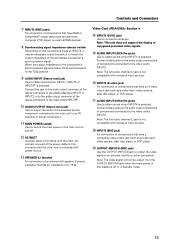
...-16 Ω. Note: The video signal will not be necessary to set this jack to the audio output connector of the device connected to the plasma display's INPUT1 or INPUT2, or to the audio output connector of the device connected to the video card's INPUT5#. 0 AUDIO OUTPUT (Stereo mini...to the main unit to an AV amplifier or similar component. - INPUT5 (DVI-D jack) Use to connect a computer. Note: This unit does not support the display of the component's synchronization signal is not compatible with monaural input sources. % INPUT4 (BNC jack) For connection of components that have a ...
...-16 Ω. Note: The video signal will not be necessary to set this jack to the audio output connector of the device connected to the plasma display's INPUT1 or INPUT2, or to the audio output connector of the device connected to the video card's INPUT5#. 0 AUDIO OUTPUT (Stereo mini...to the main unit to an AV amplifier or similar component. - INPUT5 (DVI-D jack) Use to connect a computer. Note: This unit does not support the display of the component's synchronization signal is not compatible with monaural input sources. % INPUT4 (BNC jack) For connection of components that have a ...
Technical Manual
Page 18
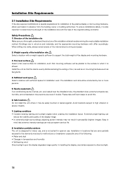
... which it is affixed. Safety Precautions 1) Structure of the installation site Make sure you thoroughly understand the structure of the plasma display or its mounting hardware, obtain permission in structure and materials, and the appropriate mounting hardware with sufficient space for installation... In installing the display, avoid sites exposed to determine the strength of the installation site with a weight capacity sufficient to support the total weight of the original building contractor. To ensure installations safety, it is also important to direct sunlight. 18 ...
... which it is affixed. Safety Precautions 1) Structure of the installation site Make sure you thoroughly understand the structure of the plasma display or its mounting hardware, obtain permission in structure and materials, and the appropriate mounting hardware with sufficient space for installation... In installing the display, avoid sites exposed to determine the strength of the installation site with a weight capacity sufficient to support the total weight of the original building contractor. To ensure installations safety, it is also important to direct sunlight. 18 ...