Technical Manual
Page 1
...PLASMA DISPLAY MONITOR: PDP-503CMX/PDP-503MXE VIDEO CARD: PDA-5002 TABLE TOP STAND: PDK-TS01 PDP BRACKET: PDK-5005 PLASMA DISPLAY WALL-MOUNT HARDWARE: PDK-5011 PLASMA DISPLAY CEILING SUSPENSION HARDWARE: PDK-5012 PLASMA DISPLAY WALL-MOUNT HARDWARE: PDK-5013 MOBILE CART: PDK-5014 CABLE COVER: PDA-P01 SPEAKER SYSTEM: PDP... the installation process and discontinue marketing activities. Before installation and preparatory work to qualified personnel, or consult the nearest PIONEER dealer for assistance. ÷ We accept no responsibility for those supplied by us. • We guarantee the ...
...PLASMA DISPLAY MONITOR: PDP-503CMX/PDP-503MXE VIDEO CARD: PDA-5002 TABLE TOP STAND: PDK-TS01 PDP BRACKET: PDK-5005 PLASMA DISPLAY WALL-MOUNT HARDWARE: PDK-5011 PLASMA DISPLAY CEILING SUSPENSION HARDWARE: PDK-5012 PLASMA DISPLAY WALL-MOUNT HARDWARE: PDK-5013 MOBILE CART: PDK-5014 CABLE COVER: PDA-P01 SPEAKER SYSTEM: PDP... the installation process and discontinue marketing activities. Before installation and preparatory work to qualified personnel, or consult the nearest PIONEER dealer for assistance. ÷ We accept no responsibility for those supplied by us. • We guarantee the ...
Technical Manual
Page 2
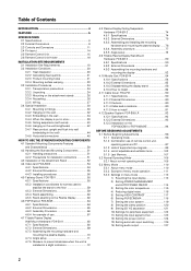
... MOUNTING COMPONENTS 4.1 Standard Mounting Components Features and Characteristics 50 4.2 Handling the Standard Mounting Components 51 4.2.1 Handling ... hardware and mounting the plasma display ...... 76 4.8.4 Assembly procedure 77 4.8.5 Angle setup 78 4.9 Tiltable Plasma Display Wall-Mount Hardware:...Speaker System: PDP-S05-LR 92 4.12.1 Specifications 92 4.12.2 External Dimensions 93 4.12.3 Installation on the PDP-503CMX or PDP-503MXE 94 BEFORE BEGINNING ADJUSTMENTS 5.1 Before Beginning Adjustments 96 5.1.1 Operating mode 96 5.1.2 Combination use of remote control unit, operating panel...
... MOUNTING COMPONENTS 4.1 Standard Mounting Components Features and Characteristics 50 4.2 Handling the Standard Mounting Components 51 4.2.1 Handling ... hardware and mounting the plasma display ...... 76 4.8.4 Assembly procedure 77 4.8.5 Angle setup 78 4.9 Tiltable Plasma Display Wall-Mount Hardware:...Speaker System: PDP-S05-LR 92 4.12.1 Specifications 92 4.12.2 External Dimensions 93 4.12.3 Installation on the PDP-503CMX or PDP-503MXE 94 BEFORE BEGINNING ADJUSTMENTS 5.1 Before Beginning Adjustments 96 5.1.1 Operating mode 96 5.1.2 Combination use of remote control unit, operating panel...
Technical Manual
Page 6
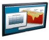
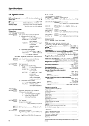
Specifications 2.1 Specifications Light-emitting panel 50-inch plasma display panel Aspect ratio 16 : 9 PEL 1280 × 768 PEL pitch 0.858 (H•RGB trio) × 0.808 (V) mm Viewing angle Horizontal: more than 160 degrees ...-related AUDIO INPUT Input Stereo mini jack (for INPUT 1/2/5) L/R ... 500mVrms/more than 10 kΩ AUDIO OUTPUT Output Stereo mini jack L/R ... 500mVrms (max)/less than 5 kΩ SPEAKER Output L/R .... 8 to 16 Ω /2 W + 2 W (at 8 Ω) # AUDIO INPUT (for INPUT 3) Input Pin jack (x2) L/R ... 500mVrms/more than 10 kΩ AUDIO INPUT (for ...
Specifications 2.1 Specifications Light-emitting panel 50-inch plasma display panel Aspect ratio 16 : 9 PEL 1280 × 768 PEL pitch 0.858 (H•RGB trio) × 0.808 (V) mm Viewing angle Horizontal: more than 160 degrees ...-related AUDIO INPUT Input Stereo mini jack (for INPUT 1/2/5) L/R ... 500mVrms/more than 10 kΩ AUDIO OUTPUT Output Stereo mini jack L/R ... 500mVrms (max)/less than 5 kΩ SPEAKER Output L/R .... 8 to 16 Ω /2 W + 2 W (at 8 Ω) # AUDIO INPUT (for INPUT 3) Input Pin jack (x2) L/R ... 500mVrms/more than 10 kΩ AUDIO INPUT (for ...

Technical Manual
Page 11
... to INPUT 1 or 2, automatically sets the POSITION and CLOCK/ PHASE to indicate error messages. Note When optional speakers have been connected, the operation panel on the unit. Operation panel on the main unit 4 STANDBY/ON button Press to put the display in the operation mode. Usage of cursor...to adjust various settings on the main unit will not be operable. 2.3 Controls and Connectors Main unit Main unit 3 Controls and Connectors Operation panel on the unit. 0 SCREEN SIZE button Press to select the screen size. - Flashes green when Power-Management function is also used to...
... to INPUT 1 or 2, automatically sets the POSITION and CLOCK/ PHASE to indicate error messages. Note When optional speakers have been connected, the operation panel on the unit. Operation panel on the main unit 4 STANDBY/ON button Press to put the display in the operation mode. Usage of cursor...to adjust various settings on the main unit will not be operable. 2.3 Controls and Connectors Main unit Main unit 3 Controls and Connectors Operation panel on the unit. 0 SCREEN SIZE button Press to select the screen size. - Flashes green when Power-Management function is also used to...

Technical Manual
Page 12
... SYNC) R HD VD 7Ω5Ô2k.Ω2 AUDIO INPUT OUTPUT (INPUT1/2) 56 7 89 0 Plasma Display Section 1 SPEAKER (R) terminal For connection of sets are controlled collectively. (See "5.6 Combination Connection") Please use a mini DIN...-16 Ω. 2 CONTROL IN/OUT (monaural mini jacks) For connection of PIONEER components that the sink level of 5 including the set that have RGB or ... COMBINATION IN/OUT Used when a number of an external right speaker. Controls and Connectors Connection Panel AC INLET OFF ON - = INPUT5 DIGITAL RGB AUDIO R INPUT3 S-VIDEO L AUDIO R INPUT4 ...
... SYNC) R HD VD 7Ω5Ô2k.Ω2 AUDIO INPUT OUTPUT (INPUT1/2) 56 7 89 0 Plasma Display Section 1 SPEAKER (R) terminal For connection of sets are controlled collectively. (See "5.6 Combination Connection") Please use a mini DIN...-16 Ω. 2 CONTROL IN/OUT (monaural mini jacks) For connection of PIONEER components that the sink level of 5 including the set that have RGB or ... COMBINATION IN/OUT Used when a number of an external right speaker. Controls and Connectors Connection Panel AC INLET OFF ON - = INPUT5 DIGITAL RGB AUDIO R INPUT3 S-VIDEO L AUDIO R INPUT4 ...
Technical Manual
Page 13
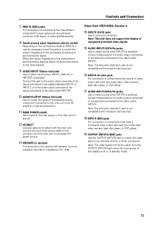
... computer, DVD player, or external RGB decoder. 8 Synchronizing signal impedance selector switch Depending on and off or in standby mode. 13 Connect a speaker that has an impedance of the selected source component connected to the main unit to an AV amplifier or similar component. - Note: The left... of the component's synchronization signal is below 75 Ω, set this jack to the audio output connector of the device connected to the plasma display's INPUT1 or INPUT2, or to the audio output connector of the device connected to the video card's INPUT5#. 0 AUDIO OUTPUT (Stereo...
... computer, DVD player, or external RGB decoder. 8 Synchronizing signal impedance selector switch Depending on and off or in standby mode. 13 Connect a speaker that has an impedance of the selected source component connected to the main unit to an AV amplifier or similar component. - Note: The left... of the component's synchronization signal is below 75 Ω, set this jack to the audio output connector of the device connected to the plasma display's INPUT1 or INPUT2, or to the audio output connector of the device connected to the video card's INPUT5#. 0 AUDIO OUTPUT (Stereo...


