Technical Manual
Page 2
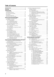
...TO USE THE STANDARD MOUNTING COMPONENTS 4.1 Standard Mounting Components Features and Characteristics 50 4.2 Handling the Standard Mounting Components 51 4.2.1 Handling precautions 51 4.2.2 Precautions...and Installing the mounting hardware and mounting the plasma display ...... 76 4.8.4 Assembly procedure 77 4.8.5 Angle setup 78 4.9 Tiltable Plasma Display Wall-Mount Hardware: PDK-5013 80 ... on the PDP-503CMX or PDP-503MXE 94 BEFORE BEGINNING ADJUSTMENTS 5.1 Before Beginning Adjustments 96 5.1.1 Operating mode 96 5.1.2 Combination use of remote control unit, operating panel and PC ...
...TO USE THE STANDARD MOUNTING COMPONENTS 4.1 Standard Mounting Components Features and Characteristics 50 4.2 Handling the Standard Mounting Components 51 4.2.1 Handling precautions 51 4.2.2 Precautions...and Installing the mounting hardware and mounting the plasma display ...... 76 4.8.4 Assembly procedure 77 4.8.5 Angle setup 78 4.9 Tiltable Plasma Display Wall-Mount Hardware: PDK-5013 80 ... on the PDP-503CMX or PDP-503MXE 94 BEFORE BEGINNING ADJUSTMENTS 5.1 Before Beginning Adjustments 96 5.1.1 Operating mode 96 5.1.2 Combination use of remote control unit, operating panel and PC ...
Technical Manual
Page 6
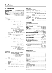
... 0.95 Consumption 380 W (NOTE 2) (1 W in standby) External dimensions (without notice. Specifications 2.1 Specifications Light-emitting panel 50-inch plasma display panel Aspect ratio 16 : 9 PEL 1280 × 768 PEL pitch 0.858 (H•RGB trio) × 0.808 ...W (at 8 Ω) # AUDIO INPUT (for INPUT 3) Input Pin jack (x2) L/R ... 500mVrms/more than 10 kΩ AUDIO INPUT (for remote control unit 1 BNC/Pin conversion adaptor 1 Connector indicator label 1 Operating Instructions 1 Warranty 1 Specifications and external designs are subject to change without attachment stand)...
... 0.95 Consumption 380 W (NOTE 2) (1 W in standby) External dimensions (without notice. Specifications 2.1 Specifications Light-emitting panel 50-inch plasma display panel Aspect ratio 16 : 9 PEL 1280 × 768 PEL pitch 0.858 (H•RGB trio) × 0.808 ...W (at 8 Ω) # AUDIO INPUT (for INPUT 3) Input Pin jack (x2) L/R ... 500mVrms/more than 10 kΩ AUDIO INPUT (for remote control unit 1 BNC/Pin conversion adaptor 1 Connector indicator label 1 Operating Instructions 1 Warranty 1 Specifications and external designs are subject to change without attachment stand)...

Technical Manual
Page 7
... preset at the factory to Installation Site Requirements.) INPUT Response Signals INPUT 1, 2 & Video signals supported # Vertical Horizontal Frequency Frequency Fv (Hz) Fh (kHz) 15.625 50 28.1 31.25 15.734 31.5 60 33.75 45.0 67.5 Signal Format Component RGB Component RGB Component RGB Component RGB Component RGB Component RGB...) Apple Macintosh 16" (1376 x 768) Figur in brackets are for 400 W ≠ 400VA of consumption per unit. This setting can be changed using either the remote control unit or a PC.
... preset at the factory to Installation Site Requirements.) INPUT Response Signals INPUT 1, 2 & Video signals supported # Vertical Horizontal Frequency Frequency Fv (Hz) Fh (kHz) 15.625 50 28.1 31.25 15.734 31.5 60 33.75 45.0 67.5 Signal Format Component RGB Component RGB Component RGB Component RGB Component RGB Component RGB...) Apple Macintosh 16" (1376 x 768) Figur in brackets are for 400 W ≠ 400VA of consumption per unit. This setting can be changed using either the remote control unit or a PC.

Technical Manual
Page 9
Rear cover: Paint (All paints are Pioneer original colors) For packaging information, refer to 3.3.2 "Unpacking". : Center of gravity 45 (Unit: mm) 609 98 1218 65 714 628 620.5 (effective screen dimensions) 1261.4 1098.2 (effective screen dimensions) 1111 294.1 Light sensor for the remote Unit operating panel MAIN POWER switch 950 (centering) Terminal area dimensions...
Rear cover: Paint (All paints are Pioneer original colors) For packaging information, refer to 3.3.2 "Unpacking". : Center of gravity 45 (Unit: mm) 609 98 1218 65 714 628 620.5 (effective screen dimensions) 1261.4 1098.2 (effective screen dimensions) 1111 294.1 Light sensor for the remote Unit operating panel MAIN POWER switch 950 (centering) Terminal area dimensions...

Technical Manual
Page 10
External Dimensions ø15.2 22.5 14 105 STANDBY/ON INPUT MENU ADJUST SET SCREEN SIZE AUTO SET UP 85.5 39 10
External Dimensions ø15.2 22.5 14 105 STANDBY/ON INPUT MENU ADJUST SET SCREEN SIZE AUTO SET UP 85.5 39 10

Technical Manual
Page 11
2.3 Controls and Connectors Main unit Main unit 3 Controls and Connectors Operation panel on the main unit 4 5 6 7 8 9 0 - 1 2 Main unit 1 Display stand 2 Remote control sensor Point the remote control toward the remote sensor to operate the unit. 3 STANDBY/ON indicator This indicator is red during standby mode,...pattern is clearly indicated in operation or standby mode. 5 KEY LOCK/UNLOCK Button (concealed button) This switches between main unit panel and remote control operation permitted/forbidden. 6 INPUT button Press to select input. 7 MENU button Press to open and close the on the...
2.3 Controls and Connectors Main unit Main unit 3 Controls and Connectors Operation panel on the main unit 4 5 6 7 8 9 0 - 1 2 Main unit 1 Display stand 2 Remote control sensor Point the remote control toward the remote sensor to operate the unit. 3 STANDBY/ON indicator This indicator is red during standby mode,...pattern is clearly indicated in operation or standby mode. 5 KEY LOCK/UNLOCK Button (concealed button) This switches between main unit panel and remote control operation permitted/forbidden. 6 INPUT button Press to select input. 7 MENU button Press to open and close the on the...

Technical Manual
Page 12
...VD 7Ω5Ô2k.Ω2 AUDIO INPUT OUTPUT (INPUT1/2) 56 7 89 0 Plasma Display Section 1 SPEAKER (R) terminal For connection of 5 including the set the number...2kΩ terminal time. But a condition for adjustments by the wired remote control RV-V107. 3 COMBINATION IN/OUT Used when a number of ...8486;. 2 CONTROL IN/OUT (monaural mini jacks) For connection of PIONEER components that have RGB or component# output jacks such as a personal...the video signal to . Controls and Connectors Connection Panel AC INLET OFF ON - = INPUT5 DIGITAL RGB AUDIO R INPUT3 S-VIDEO L AUDIO R INPUT4 ...
...VD 7Ω5Ô2k.Ω2 AUDIO INPUT OUTPUT (INPUT1/2) 56 7 89 0 Plasma Display Section 1 SPEAKER (R) terminal For connection of 5 including the set the number...2kΩ terminal time. But a condition for adjustments by the wired remote control RV-V107. 3 COMBINATION IN/OUT Used when a number of ...8486;. 2 CONTROL IN/OUT (monaural mini jacks) For connection of PIONEER components that have RGB or component# output jacks such as a personal...the video signal to . Controls and Connectors Connection Panel AC INLET OFF ON - = INPUT5 DIGITAL RGB AUDIO R INPUT3 S-VIDEO L AUDIO R INPUT4 ...
Technical Manual
Page 15
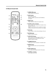
.... 0 POINT ZOOM button Use to select and enlarge one part of the screen. - VOLUME (+/-) buttons Use to adjust or enter various settings on the unit. Remote Control Unit 1 SCREEN SIZE button Press to select the screen size. 2 INPUT buttons Use to select the input. ( , , and are used when the PDA-5002...
.... 0 POINT ZOOM button Use to select and enlarge one part of the screen. - VOLUME (+/-) buttons Use to adjust or enter various settings on the unit. Remote Control Unit 1 SCREEN SIZE button Press to select the screen size. 2 INPUT buttons Use to select the input. ( , , and are used when the PDA-5002...

Technical Manual
Page 16
Area of remote control unit holder attachment Example of the main unit or some other fixed surface, so that it will be available for putting away the remote control unit when it is not in the remote control unit holder. 16 Remote Control Unit Holder 2.6 Remote Control Unit Holder Peel the sticker paper off of the lower and upper tape on the rear side of the remote control unit holder, and attach it to the rear of remote control unit holder attachment Remote control unit Remote control unit holder Upper and lower tape (NOTE) Do not obstruct the ventilation holes in use.
Area of remote control unit holder attachment Example of the main unit or some other fixed surface, so that it will be available for putting away the remote control unit when it is not in the remote control unit holder. 16 Remote Control Unit Holder 2.6 Remote Control Unit Holder Peel the sticker paper off of the lower and upper tape on the rear side of the remote control unit holder, and attach it to the rear of remote control unit holder attachment Remote control unit Remote control unit holder Upper and lower tape (NOTE) Do not obstruct the ventilation holes in use.

Technical Manual
Page 19
...; Operating temperatures: 0 to 40 °C (largely depending on the image displayed. 19 Consult Pioneer authorized dealers for an hour or so. In such cases, move them further away from an ...: • Failure to inspect the power. • Significant voltage drop between the circuit panel and the plasma display • Significant changes in voltage when switching the unit power on or off for assistance... added together when multiple units are connected, increase the number of the unit's own remote control may effect the voltage output. If condensation occurs, turn the unit off and leave...
...; Operating temperatures: 0 to 40 °C (largely depending on the image displayed. 19 Consult Pioneer authorized dealers for an hour or so. In such cases, move them further away from an ...: • Failure to inspect the power. • Significant voltage drop between the circuit panel and the plasma display • Significant changes in voltage when switching the unit power on or off for assistance... added together when multiple units are connected, increase the number of the unit's own remote control may effect the voltage output. If condensation occurs, turn the unit off and leave...

Technical Manual
Page 24
... instructions on the upper face of the carton 4 Pad 5 Pad (Common) 6 Pad 2 7 Pad 8 Miller mat 9 Power cord 4 10 Remote control unit 11 2 manganese AA batteries, R6P 12 Operating instructions 19 5 13 Warranty card 14 Display stand 15 Wiping cloth 9 16 Binder Assembly 17... injury or damage, do not lift the package by two or more than three units high. Please take precations to sofely ship the Plasma Display. No. When doing so, it is mode off grass. Installation Procedures 3.3 Installation Procedures 3.3.1 Transportation precautions 1 Any transportation of ...
... instructions on the upper face of the carton 4 Pad 5 Pad (Common) 6 Pad 2 7 Pad 8 Miller mat 9 Power cord 4 10 Remote control unit 11 2 manganese AA batteries, R6P 12 Operating instructions 19 5 13 Warranty card 14 Display stand 15 Wiping cloth 9 16 Binder Assembly 17... injury or damage, do not lift the package by two or more than three units high. Please take precations to sofely ship the Plasma Display. No. When doing so, it is mode off grass. Installation Procedures 3.3 Installation Procedures 3.3.1 Transportation precautions 1 Any transportation of ...


