Operating Instructions
Page 5
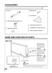
...) Operating Instructions (x1) CD-ROM(Driver software disc) (x1) Driver Installation Guide (x1) NAME AND FUNCTION OF PARTS Main Unit 18 En Power indicator (Lights green when ON) IR transmitting filter PEN NORMAL Rear side of more clearly delineated characters and lines. Using the special pen allows the...however, compared to write on the screen. ACCESSORIES Using this mode, your finger or other device to input characters and lines on , the power indicator will flash orange; PEN Mode: In this mode, the special accessory pen can be used to drawing with whether you will use the...
...) Operating Instructions (x1) CD-ROM(Driver software disc) (x1) Driver Installation Guide (x1) NAME AND FUNCTION OF PARTS Main Unit 18 En Power indicator (Lights green when ON) IR transmitting filter PEN NORMAL Rear side of more clearly delineated characters and lines. Using the special pen allows the...however, compared to write on the screen. ACCESSORIES Using this mode, your finger or other device to input characters and lines on , the power indicator will flash orange; PEN Mode: In this mode, the special accessory pen can be used to drawing with whether you will use the...
Operating Instructions
Page 8
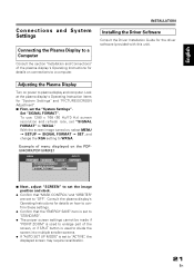
...The proper screen settings cannot be made if "POINT ZOOM" is used to enlarge part of menu displayed on the PDP504CMX/PDP-50MXE1 MENU INPUT1 PICTURE SCREEN SETUP OPTION POWER MANAGEMENT CLAMP POSITION SIGNAL FORMAT : OFF : AUTO : XGA 7 Next, adjust "SCREEN" to set the image position... FORMAT = SET, and change the XGA setting to "WXGA." Look at the plasma display's Operating Instruction items for the driver software (provided with this unit). Adjusting the Plasma Display Turn on power to a computer. Chinese Español Nederlands Italiano Deutsch Français English Connections...
...The proper screen settings cannot be made if "POINT ZOOM" is used to enlarge part of menu displayed on the PDP504CMX/PDP-50MXE1 MENU INPUT1 PICTURE SCREEN SETUP OPTION POWER MANAGEMENT CLAMP POSITION SIGNAL FORMAT : OFF : AUTO : XGA 7 Next, adjust "SCREEN" to set the image position... FORMAT = SET, and change the XGA setting to "WXGA." Look at the plasma display's Operating Instruction items for the driver software (provided with this unit). Adjusting the Plasma Display Turn on power to a computer. Chinese Español Nederlands Italiano Deutsch Français English Connections...
Operating Instructions
Page 9
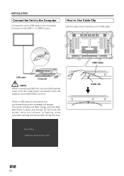
Do not touch the screen while the indicator is connected, the accompanying screen message will appear: The power indicator will flash orange, and then flash alternately in green and orange. INSTALLATION Connect the Unit to the Computer Connect the unit's USB cable to ... automatic settings are being made during this time. USB Cable Cable clip 22 En USB cable Computer NOTE: When connecting a USB hub, use only self-powered types (with AC outlet power connection) with the capacity to hold the unit's USB cable.
Do not touch the screen while the indicator is connected, the accompanying screen message will appear: The power indicator will flash orange, and then flash alternately in green and orange. INSTALLATION Connect the Unit to the Computer Connect the unit's USB cable to ... automatic settings are being made during this time. USB Cable Cable clip 22 En USB cable Computer NOTE: When connecting a USB hub, use only self-powered types (with AC outlet power connection) with the capacity to hold the unit's USB cable.
Operating Instructions
Page 11
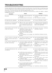
.... ÷ Install driver software correctly. 24 En Cursor position diverges from another component. USB cable is not turned on. ÷ Turn on power to turn on. ÷ The holes in rear end of pen are blocked. ÷ The pen is being used outside of pen tip ...after checking the following items, contact your dealer or nearest PIONEER service center. If you think there is disconnected. ÷ Connect USB cable correctly. Sometimes the trouble may not be rectified even after initial setting. ÷ The plasma display's AUTO SET UP screen position adjustment has been reset...
.... ÷ Install driver software correctly. 24 En Cursor position diverges from another component. USB cable is not turned on. ÷ Turn on power to turn on. ÷ The holes in rear end of pen are blocked. ÷ The pen is being used outside of pen tip ...after checking the following items, contact your dealer or nearest PIONEER service center. If you think there is disconnected. ÷ Connect USB cable correctly. Sometimes the trouble may not be rectified even after initial setting. ÷ The plasma display's AUTO SET UP screen position adjustment has been reset...
Operating Instructions
Page 12
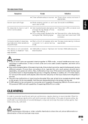
... to promote long life and optimum performance, regular cleaning is loose or has been ÷ Connect USB cable securely. CAUTION: Never use an AC powered USB hub with a dry, soft cloth. mes- In the case of severe soiling, dip a soft cloth in some places. ÷ User... ÷ USB cable is recommended. CAUTION: ÷ If two or more than the actual tip of the unit and pen may occur, resulting in power-saving appropriate. disconnected. sage "Now setting....") ÷ Dirt or other object blocked infra- ÷ Remove dirt or other obstruction; reconnect. rear is ...
... to promote long life and optimum performance, regular cleaning is loose or has been ÷ Connect USB cable securely. CAUTION: Never use an AC powered USB hub with a dry, soft cloth. mes- In the case of severe soiling, dip a soft cloth in some places. ÷ User... ÷ USB cable is recommended. CAUTION: ÷ If two or more than the actual tip of the unit and pen may occur, resulting in power-saving appropriate. disconnected. sage "Now setting....") ÷ Dirt or other object blocked infra- ÷ Remove dirt or other obstruction; reconnect. rear is ...
Operating Instructions
Page 13
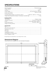
...Power indicator ...LED Interface ...USB 1.1 Power supply self-powered from USB port Power consumption Maximum 2.5W External dimensions (including plasma display, excluding pen stand 1,258 (W) x 758 (H) x 115 (D) mm Weight (excluding plasma display, including pen stand[0.6 kg 7.4 kg Dedicated Pen Transmission Ultrasonic wave Operation switches Pen tip (x1), Body (x2) Power... may change without notice. Copyright © 2004 Pioneer Corporation. All rights reserved. Dimensional Diagram (View when this unit installed on the PDP-504CMX/PDP-50MXE1) 1258 115 92 74 (excluding the bolt...
...Power indicator ...LED Interface ...USB 1.1 Power supply self-powered from USB port Power consumption Maximum 2.5W External dimensions (including plasma display, excluding pen stand 1,258 (W) x 758 (H) x 115 (D) mm Weight (excluding plasma display, including pen stand[0.6 kg 7.4 kg Dedicated Pen Transmission Ultrasonic wave Operation switches Pen tip (x1), Body (x2) Power... may change without notice. Copyright © 2004 Pioneer Corporation. All rights reserved. Dimensional Diagram (View when this unit installed on the PDP-504CMX/PDP-50MXE1) 1258 115 92 74 (excluding the bolt...
Technical Manual
Page 2
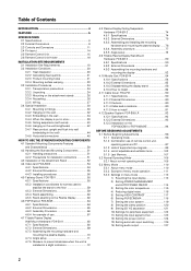
...MOUNTING COMPONENTS 4.1 Standard Mounting Components Features and Characteristics 50 4.2 Handling the Standard Mounting Components 51 4.2.1 ...hardware and mounting the plasma display ...... 76 4.8.4 Assembly procedure 77 4.8.5 Angle setup 78 4.9 Tiltable Plasma Display Wall-Mount Hardware...PDP-503CMX or PDP-503MXE 94 BEFORE BEGINNING ADJUSTMENTS 5.1 Before Beginning Adjustments 96 5.1.1 Operating mode 96 5.1.2 Combination use of remote control unit, operating panel... 1) Rewriting the input display 113 2) Setting POWER MANAGEMENT and AUTO POWER ON/OFF 114 3) Setting the color temperature ...
...MOUNTING COMPONENTS 4.1 Standard Mounting Components Features and Characteristics 50 4.2 Handling the Standard Mounting Components 51 4.2.1 ...hardware and mounting the plasma display ...... 76 4.8.4 Assembly procedure 77 4.8.5 Angle setup 78 4.9 Tiltable Plasma Display Wall-Mount Hardware...PDP-503CMX or PDP-503MXE 94 BEFORE BEGINNING ADJUSTMENTS 5.1 Before Beginning Adjustments 96 5.1.1 Operating mode 96 5.1.2 Combination use of remote control unit, operating panel... 1) Rewriting the input display 113 2) Setting POWER MANAGEMENT and AUTO POWER ON/OFF 114 3) Setting the color temperature ...
Technical Manual
Page 5
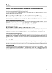
... depending on the input signal. Further, use . Unnecessary frequency components of the power-control function provides a 20% reduction in lighted locations. Features Features and Functions of the PDP-503CMX/PDP-503MXE Plasma Display Introduces newly developed 50" XGA Wide Plasma Panel The new high-precision XGA 50" wide plasma panel pushes the envelope of 1280x1024 (SXGA) and 1600x1200 (UXGA) are also...
... depending on the input signal. Further, use . Unnecessary frequency components of the power-control function provides a 20% reduction in lighted locations. Features Features and Functions of the PDP-503CMX/PDP-503MXE Plasma Display Introduces newly developed 50" XGA Wide Plasma Panel The new high-precision XGA 50" wide plasma panel pushes the envelope of 1280x1024 (SXGA) and 1600x1200 (UXGA) are also...
Technical Manual
Page 6
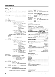
Specifications 2.1 Specifications Light-emitting panel 50-inch plasma display panel Aspect ratio 16 : 9 PEL 1280 × 768 PEL pitch 0.858 (H•RGB trio) × 0.808 (V) mm Viewing angle Horizontal: more than 160 degrees ...NOTE 1) Combination In/Out Terminal: Mini-DIN, 6-pin Control In/Out Terminal: Monaural mini-jack (× 2) Power requirements AC 100 V to 120 V, 50/60 Hz In-rush less than 30 A Power factor more than three tiers Standard accessories Power cord 1 Remote control unit 1 AA battery 2 Wiping cloth 1 Speed clamp 2 Bead Band 2 Operating instructions 1...
Specifications 2.1 Specifications Light-emitting panel 50-inch plasma display panel Aspect ratio 16 : 9 PEL 1280 × 768 PEL pitch 0.858 (H•RGB trio) × 0.808 (V) mm Viewing angle Horizontal: more than 160 degrees ...NOTE 1) Combination In/Out Terminal: Mini-DIN, 6-pin Control In/Out Terminal: Monaural mini-jack (× 2) Power requirements AC 100 V to 120 V, 50/60 Hz In-rush less than 30 A Power factor more than three tiers Standard accessories Power cord 1 Remote control unit 1 AA battery 2 Wiping cloth 1 Speed clamp 2 Bead Band 2 Operating instructions 1...

Technical Manual
Page 9
...paints are Pioneer original colors) For packaging information, refer to 3.3.2 "Unpacking". : Center of gravity 45 (Unit: mm) 609 98 1218 65 714 628 620.5 (effective screen dimensions) 1261.4 1098.2 (effective screen dimensions) 1111 294.1 Light sensor for the remote Unit operating panel MAIN POWER switch 950... (centering) Terminal area dimensions Rear View 1162 104 590 104 250 660 150 150 250 496 20-M8 (φ16 mm, with hole rivet) 9 Rear cover: Aluminum, Front protector panel: Glass Treatment: Front: Paint...
...paints are Pioneer original colors) For packaging information, refer to 3.3.2 "Unpacking". : Center of gravity 45 (Unit: mm) 609 98 1218 65 714 628 620.5 (effective screen dimensions) 1261.4 1098.2 (effective screen dimensions) 1111 294.1 Light sensor for the remote Unit operating panel MAIN POWER switch 950... (centering) Terminal area dimensions Rear View 1162 104 590 104 250 660 150 150 250 496 20-M8 (φ16 mm, with hole rivet) 9 Rear cover: Aluminum, Front protector panel: Glass Treatment: Front: Paint...

Technical Manual
Page 11
... display. 9 SET button Press to green when the unit is clearly indicated in the operation mode. Note When optional speakers have been connected, the operation panel on the main unit 4 5 6 7 8 9 0 - 1 2 Main unit 1 Display stand 2 Remote control sensor Point the remote control toward the remote sensor to operate ... turns to adjust or enter various settings on the unit. 2.3 Controls and Connectors Main unit Main unit 3 Controls and Connectors Operation panel on the main unit will not be operable. Flashes green when Power-Management function is also used to optimum values. 11
... display. 9 SET button Press to green when the unit is clearly indicated in the operation mode. Note When optional speakers have been connected, the operation panel on the main unit 4 5 6 7 8 9 0 - 1 2 Main unit 1 Display stand 2 Remote control sensor Point the remote control toward the remote sensor to operate ... turns to adjust or enter various settings on the unit. 2.3 Controls and Connectors Main unit Main unit 3 Controls and Connectors Operation panel on the main unit will not be operable. Flashes green when Power-Management function is also used to optimum values. 11

Technical Manual
Page 12
...jacks such as the connecting cable. (NOTE) It has no ABL linking function. Controls and Connectors Connection Panel AC INLET OFF ON - = INPUT5 DIGITAL RGB AUDIO R INPUT3 S-VIDEO L AUDIO R INPUT4 VIDEO...HD VD 7Ω5Ô2k.Ω2 AUDIO INPUT OUTPUT (INPUT1/2) 56 7 89 0 Plasma Display Section 1 SPEAKER (R) terminal For connection of sets are controlled collectively. (See "5.6...output from the OUTPUT (INPUT1) connector when the main power of this display is off . 12 4 RS-... input and output is that the sink level of PIONEER components that the signal is 8 -16 Ω....
...jacks such as the connecting cable. (NOTE) It has no ABL linking function. Controls and Connectors Connection Panel AC INLET OFF ON - = INPUT5 DIGITAL RGB AUDIO R INPUT3 S-VIDEO L AUDIO R INPUT4 VIDEO...HD VD 7Ω5Ô2k.Ω2 AUDIO INPUT OUTPUT (INPUT1/2) 56 7 89 0 Plasma Display Section 1 SPEAKER (R) terminal For connection of sets are controlled collectively. (See "5.6...output from the OUTPUT (INPUT1) connector when the main power of this display is off . 12 4 RS-... input and output is that the sink level of PIONEER components that the signal is 8 -16 Ω....
Technical Manual
Page 13
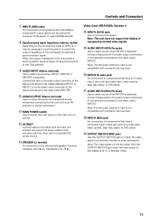
...this connector and the other component. When the output impedance of the component's synchronization signal is below 75 Ω, set this switch to a standard AC power source. ~ SPEAKER (L) terminal For connection of an external left speaker. Connect a speaker that has an impedance of 8 -16 Ω. Note: The... INPUT5 (DVI-D jack) Use to the video card's INPUT4. Connect this jack to the audio output connector of the device connected to the plasma display's INPUT1 or INPUT2, or to the audio output connector of the device connected to the video card's INPUT5#. 0 AUDIO OUTPUT (Stereo mini...
...this connector and the other component. When the output impedance of the component's synchronization signal is below 75 Ω, set this switch to a standard AC power source. ~ SPEAKER (L) terminal For connection of an external left speaker. Connect a speaker that has an impedance of 8 -16 Ω. Note: The... INPUT5 (DVI-D jack) Use to the video card's INPUT4. Connect this jack to the audio output connector of the device connected to the plasma display's INPUT1 or INPUT2, or to the audio output connector of the device connected to the video card's INPUT5#. 0 AUDIO OUTPUT (Stereo mini...

Technical Manual
Page 14
... connection) 5 NC (No connection) 6 DDC Clock 7 DDC Data 8 NC (No connection) 9 T.M.D.S. Data1- 10 T.M.D.S. Data1/3 Shield 12 NC (No connection) 13 NC (No connection) 14 +5V Power 15 GND 16 Hot Plug Detect 17 T.M.D.S. Data0+ 19 T.M.D.S. Combination IN 1 GND 2 NC (not connected) 3 TxD (output) 4 NC (not connected) 5 RxD (input) 6 NC (not connected...
... connection) 5 NC (No connection) 6 DDC Clock 7 DDC Data 8 NC (No connection) 9 T.M.D.S. Data1- 10 T.M.D.S. Data1/3 Shield 12 NC (No connection) 13 NC (No connection) 14 +5V Power 15 GND 16 Hot Plug Detect 17 T.M.D.S. Data0+ 19 T.M.D.S. Combination IN 1 GND 2 NC (not connected) 3 TxD (output) 4 NC (not connected) 5 RxD (input) 6 NC (not connected...

Technical Manual
Page 19
...to increase the room temperature gradually. Beware of the following occurs, contact an electrician to inspect the power. • Significant voltage drop between the circuit panel and the plasma display • Significant changes in the wiring system. 12) Effective remote control distance This display emits...within a value stipulated by standards in each country flows from the display or contact Pioneer authorized dealer for 400 W ≠ 400 VA of the unit's own remote control may result in a power distribution series, choose the leakage breaker rating so that it off • When ...
...to increase the room temperature gradually. Beware of the following occurs, contact an electrician to inspect the power. • Significant voltage drop between the circuit panel and the plasma display • Significant changes in the wiring system. 12) Effective remote control distance This display emits...within a value stipulated by standards in each country flows from the display or contact Pioneer authorized dealer for 400 W ≠ 400 VA of the unit's own remote control may result in a power distribution series, choose the leakage breaker rating so that it off • When ...
Technical Manual
Page 21
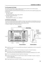
...Pioneer. Take precautions to make sure that can be regarded as shown in the unit. Always turn every bolt by hand 2 or 3 times and check to prevent soiling walls behind the product with a torque between 50 and 80 kg/cm. Please make sure it is transformed into heat, power... consumption may lead to the unit using mounting hardware available from the air outlets. For power consumption, allow for ventilation on the rear panel. b holes b holes b holes Vent (fan...
...Pioneer. Take precautions to make sure that can be regarded as shown in the unit. Always turn every bolt by hand 2 or 3 times and check to prevent soiling walls behind the product with a torque between 50 and 80 kg/cm. Please make sure it is transformed into heat, power... consumption may lead to the unit using mounting hardware available from the air outlets. For power consumption, allow for ventilation on the rear panel. b holes b holes b holes Vent (fan...
Technical Manual
Page 23
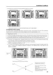
... warp is found to the illustration below, diagonally extend string of distortion. A A Mount bolt holes Plasma Display Mount Surface (Mount Brackets) A String F E String C D Magnified view of section A Point E is expressed by Pioneer, perform the following to confirm that the warp of up to 3mm. Any value of L greater ...than 0 indicates the presence of maximum φ 0.1-mm diameter through the bolt mount openings. Point F is negligible. In order to prevent pinching the power cord or signal cables.) 3.2.4 Mounting surface warping The display section incorporates glass.
... warp is found to the illustration below, diagonally extend string of distortion. A A Mount bolt holes Plasma Display Mount Surface (Mount Brackets) A String F E String C D Magnified view of section A Point E is expressed by Pioneer, perform the following to confirm that the warp of up to 3mm. Any value of L greater ...than 0 indicates the presence of maximum φ 0.1-mm diameter through the bolt mount openings. Point F is negligible. In order to prevent pinching the power cord or signal cables.) 3.2.4 Mounting surface warping The display section incorporates glass.

Technical Manual
Page 24
... is important to sofely ship the Plasma Display. When doing so, it is mode off grass. Terms 1 Upper face of the carton 2 Carton cover 3 Lower face of the carton 4 Pad 5 Pad (Common) 6 Pad 2 7 Pad 8 Miller mat 9 Power cord 4 10 Remote control unit 11 2 manganese AA batteries, R6P 12 ... instructions 19 5 13 Warranty card 14 Display stand 15 Wiping cloth 9 16 Binder Assembly 17 Bolt, Washer 20 18 Remote control unit holder 19 Power cord case 20 Accessory case 13 8 21 (Inside the mirror mat) 6 21 Front sheet 7 3 (These accessories are inside the accessory case.)...
... is important to sofely ship the Plasma Display. When doing so, it is mode off grass. Terms 1 Upper face of the carton 2 Carton cover 3 Lower face of the carton 4 Pad 5 Pad (Common) 6 Pad 2 7 Pad 8 Miller mat 9 Power cord 4 10 Remote control unit 11 2 manganese AA batteries, R6P 12 ... instructions 19 5 13 Warranty card 14 Display stand 15 Wiping cloth 9 16 Binder Assembly 17 Bolt, Washer 20 18 Remote control unit holder 19 Power cord case 20 Accessory case 13 8 21 (Inside the mirror mat) 6 21 Front sheet 7 3 (These accessories are inside the accessory case.)...

Technical Manual
Page 25
... 1 Remove the packing bands. 2 Slowly lift and remove the upper carton. 3 Lift and remove the carton cover. 4 Remove the pads. 5 Remove the accessory case and power cord case. 6 Remove the unit. (This should be lifted by two persons. • Never move the unit by dragging it needs to be moved, the... unpacking, are complete. 25 If it along the floor. • Move the unit slowly, taking care to prevent scraping or striking the delicate front protective panel. • In order to prevent adhesion of the unpacked unit.
... 1 Remove the packing bands. 2 Slowly lift and remove the upper carton. 3 Lift and remove the carton cover. 4 Remove the pads. 5 Remove the accessory case and power cord case. 6 Remove the unit. (This should be lifted by two persons. • Never move the unit by dragging it needs to be moved, the... unpacking, are complete. 25 If it along the floor. • Move the unit slowly, taking care to prevent scraping or striking the delicate front protective panel. • In order to prevent adhesion of the unpacked unit.

