Operating Instructions
Page 2
...OF CONFORMITY This device complies with Video Card Model Number: PDP-504CMX/PDP-434CMX (Plasma Display) PDA-5003/PDA-5004 (Video Card) Product Category: Class B Personal Computers & Peripherals Responsible Party Name: PIONEER ELECTRONICS (USA) INC. Operation is subject to the following installations which the receiver is connected....NOTE: This equipment has been tested and found to comply with the limits for help. These limits are designed to consult your Pioneer dealer first. BOX 1760, LONG BEACH, CA., 90801-1760 U.S.A. NO USER-SERVICEABLE PARTS INSIDE. This equipment generates, uses,...
...OF CONFORMITY This device complies with Video Card Model Number: PDP-504CMX/PDP-434CMX (Plasma Display) PDA-5003/PDA-5004 (Video Card) Product Category: Class B Personal Computers & Peripherals Responsible Party Name: PIONEER ELECTRONICS (USA) INC. Operation is subject to the following installations which the receiver is connected....NOTE: This equipment has been tested and found to comply with the limits for help. These limits are designed to consult your Pioneer dealer first. BOX 1760, LONG BEACH, CA., 90801-1760 U.S.A. NO USER-SERVICEABLE PARTS INSIDE. This equipment generates, uses,...
Operating Instructions
Page 4
...50MXE1/PDP-50MXE1-S (or PDP-434CMX/PDP-43MXE1/PDP-43MXE1-S) plasma display has been originally designed as a computer monitor, but by installing the optional PDA-5003/PDA-5004 video card, the following supplementary features are produced: 1. Contents Safety Precautions i Before Proceeding 2 Checking supplied... video equipment. The PDA-5003/PDA-5004 is a video card designed for purchasing this manual 2 Part Names and Functions 4 Connection panel 4 Installation and Connections 6 Installing the video card 6 Input connectors on the plasma display with the Pioneer Plasma Display PDP-504CMX...
...50MXE1/PDP-50MXE1-S (or PDP-434CMX/PDP-43MXE1/PDP-43MXE1-S) plasma display has been originally designed as a computer monitor, but by installing the optional PDA-5003/PDA-5004 video card, the following supplementary features are produced: 1. Contents Safety Precautions i Before Proceeding 2 Checking supplied... video equipment. The PDA-5003/PDA-5004 is a video card designed for purchasing this manual 2 Part Names and Functions 4 Connection panel 4 Installation and Connections 6 Installing the video card 6 Input connectors on the plasma display with the Pioneer Plasma Display PDP-504CMX...

Operating Instructions
Page 6
... RESET], then press the SET button. Before Proceeding Note The screen images depicted in these adjustments for your Plasma Display regarding PICTURE adjustment when inputting computer signals. MENU PICTURE SCREEN CONTRAST : BRIGHTNESS : COLOR : TINT : SHARPNESS : SETUP 0 0 0 0 0 PICTURE RESET INPUT1 OPTION 4 Press the SET button. TINT Adjust so that the picture can...
... RESET], then press the SET button. Before Proceeding Note The screen images depicted in these adjustments for your Plasma Display regarding PICTURE adjustment when inputting computer signals. MENU PICTURE SCREEN CONTRAST : BRIGHTNESS : COLOR : TINT : SHARPNESS : SETUP 0 0 0 0 0 PICTURE RESET INPUT1 OPTION 4 Press the SET button. TINT Adjust so that the picture can...
Operating Instructions
Page 7
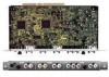
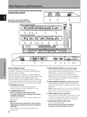
... personal computer or external RGB decoder; Connect this connector without first consulting your Pioneer installation technician. ANALOG RGB INPUT5 AUDIO IN OUT R L G(ON SYNC) B R HD (H/V SYNC) VD R L ~ !@ # When installing PDA-5004 S-VIDEO ... 2 video input connectors, 1 video output connector, audio input/output jacks and speaker terminals. When this display is installed on a plasma display, an additional three sets of... (page 15). 7 DIGITAL RGB (INPUT2) (DVI-D jack) Use to an external monitor or other component. See the pages noted in standby mode (page 10). 6 AUDIO ...
... personal computer or external RGB decoder; Connect this connector without first consulting your Pioneer installation technician. ANALOG RGB INPUT5 AUDIO IN OUT R L G(ON SYNC) B R HD (H/V SYNC) VD R L ~ !@ # When installing PDA-5004 S-VIDEO ... 2 video input connectors, 1 video output connector, audio input/output jacks and speaker terminals. When this display is installed on a plasma display, an additional three sets of... (page 15). 7 DIGITAL RGB (INPUT2) (DVI-D jack) Use to an external monitor or other component. See the pages noted in standby mode (page 10). 6 AUDIO ...
Operating Instructions
Page 8
...INPUT3 or INPUT4 (page 16). $ ANALOG RGB (INPUT5) (BNC jacks) For connecting components equipped with RGB outputs jacks, such as a personal computer or external RGB decoder; Note: The video signal will not be output from the AUDIO (OUTPUT) jack when the MAIN POWER switch is selected.... OUT (INPUT4) (BNC jack) Use the VIDEO OUT (INPUT4) jack to output the video signal to an external monitor or other end to a standard AC power source. = SPEAKER (L) terminal For connection of components connected to the video card's INPUT5 (page 15). 5 En Part Names and Functions English Connect...
...INPUT3 or INPUT4 (page 16). $ ANALOG RGB (INPUT5) (BNC jacks) For connecting components equipped with RGB outputs jacks, such as a personal computer or external RGB decoder; Note: The video signal will not be output from the AUDIO (OUTPUT) jack when the MAIN POWER switch is selected.... OUT (INPUT4) (BNC jack) Use the VIDEO OUT (INPUT4) jack to output the video signal to an external monitor or other end to a standard AC power source. = SPEAKER (L) terminal For connection of components connected to the video card's INPUT5 (page 15). 5 En Part Names and Functions English Connect...
Operating Instructions
Page 9
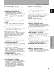
...to eliminate static electricity on the Pioneer Plasma Display PDP-504CMX/PDP-50MXE1...RGB (H/V SYNC) B R HD VD AUDIO R L PDA-5003 PDA-5004 RGB (BNC) COMPONENT Note Use a soft cloth to secure...PDA-5003 model. 1 Remove the protective cover over the video card slot on the plasma display, do not attempt to remove it since malfunction or damage may be attempted). 1 Remove the two screws holding the video card. Confirm this item before installing this video card: • Disconnect the plasma display from computer... on the plasma display's terminal panel. Installation and Connections ...
...to eliminate static electricity on the Pioneer Plasma Display PDP-504CMX/PDP-50MXE1...RGB (H/V SYNC) B R HD VD AUDIO R L PDA-5003 PDA-5004 RGB (BNC) COMPONENT Note Use a soft cloth to secure...PDA-5003 model. 1 Remove the protective cover over the video card slot on the plasma display, do not attempt to remove it since malfunction or damage may be attempted). 1 Remove the two screws holding the video card. Confirm this item before installing this video card: • Disconnect the plasma display from computer... on the plasma display's terminal panel. Installation and Connections ...
Operating Instructions
Page 10
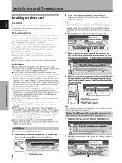
...VD Output source Video component/ personal computer (PC) G ON SYNC B R with RGB output G B R H/V SYNC G Video component with component video output Y B R HD VD Pb/Cb Pr/Cr : Do not connect anything. : Connect to the INPUT1 and INPUT5 jack. I When using PDA-5004 Input connectors on the plasma display ...18 to 20). *2 INPUT1 is compatible with Microsoft's Plug & Play (VESA DDC 1/2B). *3 Depending on the video output board of the computer, this type of connection may not be possible. *4 INPUT2 is compatible with INPUT5. Please see pages 18 to the INPUT1 ...
...VD Output source Video component/ personal computer (PC) G ON SYNC B R with RGB output G B R H/V SYNC G Video component with component video output Y B R HD VD Pb/Cb Pr/Cr : Do not connect anything. : Connect to the INPUT1 and INPUT5 jack. I When using PDA-5004 Input connectors on the plasma display ...18 to 20). *2 INPUT1 is compatible with Microsoft's Plug & Play (VESA DDC 1/2B). *3 Depending on the video output board of the computer, this type of connection may not be possible. *4 INPUT2 is compatible with INPUT5. Please see pages 18 to the INPUT1 ...

Operating Instructions
Page 11
...Please see pages 18 to 20. If necessary, use of various special trick play functions on video components. I When using PDA-5004 Connection to AV components Connection to support component video signals with component video jacks. Please see pages 18 to this Video Card... equipped with standard, stable signal levels and sync signals. English Installation and Connections INPUT5 jack Y Pb/Cb Pr/Cr Output source Video component/ personal computer (PC) with RGB output Video component with component video jacks. See Appendixes 1 and 2 (pages 43 to 20. 8 En On-screen setup ...
...Please see pages 18 to 20. If necessary, use of various special trick play functions on video components. I When using PDA-5004 Connection to AV components Connection to support component video signals with component video jacks. Please see pages 18 to this Video Card... equipped with standard, stable signal levels and sync signals. English Installation and Connections INPUT5 jack Y Pb/Cb Pr/Cr Output source Video component/ personal computer (PC) with RGB output Video component with component video jacks. See Appendixes 1 and 2 (pages 43 to 20. 8 En On-screen setup ...

Operating Instructions
Page 13
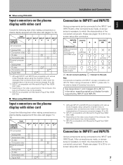
... the display is below 75 Ω remove the video card and set the impedance selector switch to make sure that the personal computer's power and display's main power is necessary after connection. If connected to 20. When the output impedance of the sync signal... connecting to ANALOG RGB (INPUT5) [Connections for PDA-5003] ANALOG RGB INPUT5 G(ON SYNC) B R HD (H/V SYNC) VD Connection to 20. 10 En Please see pages 18 to a personal computer Connection method differs depending on top of the connected computer's synchronization signal. When connecting to the VD jack...
... the display is below 75 Ω remove the video card and set the impedance selector switch to make sure that the personal computer's power and display's main power is necessary after connection. If connected to 20. When the output impedance of the sync signal... connecting to ANALOG RGB (INPUT5) [Connections for PDA-5003] ANALOG RGB INPUT5 G(ON SYNC) B R HD (H/V SYNC) VD Connection to 20. 10 En Please see pages 18 to a personal computer Connection method differs depending on top of the connected computer's synchronization signal. When connecting to the VD jack...

Operating Instructions
Page 14
...a conversion connector or adapter etc. Please see pages 18 to 20. When connecting to ANALOG RGB (INPUT5) [Connections for a personal computer with the computer or sold separately may be necessary. Note When making G ON SYNC connections, do not make any connections to ANALOG RGB OUT (INPUT1... connections for PDA-5003] ANALOG RGB INPUT5 G(ON SYNC) B R HD (H/V SYNC) VD Installation and Connections To an external monitor With the plasma display, it is possible to output the video signal to an external monitor or other component from the ANALOG RGB OUT (INPUT1) terminal when the ...
...a conversion connector or adapter etc. Please see pages 18 to 20. When connecting to ANALOG RGB (INPUT5) [Connections for a personal computer with the computer or sold separately may be necessary. Note When making G ON SYNC connections, do not make any connections to ANALOG RGB OUT (INPUT1... connections for PDA-5003] ANALOG RGB INPUT5 G(ON SYNC) B R HD (H/V SYNC) VD Installation and Connections To an external monitor With the plasma display, it is possible to output the video signal to an external monitor or other component from the ANALOG RGB OUT (INPUT1) terminal when the ...

Operating Instructions
Page 15
...selector switch to 75 Ω (page 6). are equipped with output that has the vertical synchronization signal layered on top of computer devices manufactured by Apple Computer, Inc. When connecting to ANALOG RGB IN (INPUT1) ANALOG RGB IN D-Sub ANALOG RGB OUT D-Sub INPUT1 AUDIO When...VD jack. Installation and Connections When connecting to COMPONENT VIDEO (INPUT5) [Connections for PDA-5004] COMPONENT VIDEO INPUT5 Y Pb/Cb Pr/Cr When connecting to ANALOG RGB (INPUT5) [Connections for a personal computer with both G ON SYNC and composite SYNC outputs. When the output impedance of...
...selector switch to 75 Ω (page 6). are equipped with output that has the vertical synchronization signal layered on top of computer devices manufactured by Apple Computer, Inc. When connecting to ANALOG RGB IN (INPUT1) ANALOG RGB IN D-Sub ANALOG RGB OUT D-Sub INPUT1 AUDIO When...VD jack. Installation and Connections When connecting to COMPONENT VIDEO (INPUT5) [Connections for PDA-5004] COMPONENT VIDEO INPUT5 Y Pb/Cb Pr/Cr When connecting to ANALOG RGB (INPUT5) [Connections for a personal computer with both G ON SYNC and composite SYNC outputs. When the output impedance of...
Operating Instructions
Page 16
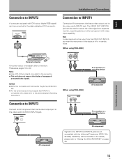
... plasma display's DVI connector. DIGITAL RGB DVI-D INPUT2 AUDIO Personal computer On-screen setup is off or in standby mode. [When using PDA-5003] VIDEO INPUT4 IN OUT To a monitor or a recording device [When using PDA-5004] VIDEO INPUT4 IN OUT AV component To a monitor or a recording device Installation and Connections AV component AV component Signals...
... plasma display's DVI connector. DIGITAL RGB DVI-D INPUT2 AUDIO Personal computer On-screen setup is off or in standby mode. [When using PDA-5003] VIDEO INPUT4 IN OUT To a monitor or a recording device [When using PDA-5004] VIDEO INPUT4 IN OUT AV component To a monitor or a recording device Installation and Connections AV component AV component Signals...
Operating Instructions
Page 23
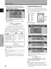
...with the component you are appropriate and available for INPUT 1 or INPUT 5. ÷ The [COLOR DECODING] setting is not supported when inputting a computer signal, or when the [SIGNAL FORMAT] function has been used to select a signal other than [525p] or [750p]. 20 En [CLAMP ...menu screen. Please take care when making settings. Set [SIGNAL FORMAT] and [COLOR DECODING] as follows each applicable input (PDA-5003: INPUT1 or INPUT5, PDA-5004: INPUT1). ÷ When using . Connected component SETUP SIGNAL FORMAT COLOR DECODING Component video output of connections made. Mode ...
...with the component you are appropriate and available for INPUT 1 or INPUT 5. ÷ The [COLOR DECODING] setting is not supported when inputting a computer signal, or when the [SIGNAL FORMAT] function has been used to select a signal other than [525p] or [750p]. 20 En [CLAMP ...menu screen. Please take care when making settings. Set [SIGNAL FORMAT] and [COLOR DECODING] as follows each applicable input (PDA-5003: INPUT1 or INPUT5, PDA-5004: INPUT1). ÷ When using . Connected component SETUP SIGNAL FORMAT COLOR DECODING Component video output of connections made. Mode ...

Operating Instructions
Page 24
The ON indicator on the screen. If no connections are made to these terminals, on-screen setup is turned off . • If the input computer signal is a result of residual electric load impressed on -screen menu to input signals from components connected to turn the power ON....light for a long time. Before you begin, make sure you have: • Made connections between the plasma display and AV components or personal computer as described in the section "Installation and Connections" starting on and off presently. The STANDBY indicator on the front panel will light red. 2 Press...
The ON indicator on the screen. If no connections are made to these terminals, on-screen setup is turned off . • If the input computer signal is a result of residual electric load impressed on -screen menu to input signals from components connected to turn the power ON....light for a long time. Before you begin, make sure you have: • Made connections between the plasma display and AV components or personal computer as described in the section "Installation and Connections" starting on and off presently. The STANDBY indicator on the front panel will light red. 2 Press...

Operating Instructions
Page 26
...'s intentions. Although these modes are viewing. FULL Suitable for viewing "Vista vision" cinema sizes. Provides a more expansive, powerful image. English Changing screen size The plasma display incorporates screen modes of authors protected under copyright law. &#... for wide screen images (squeeze). Operation Remote control unit SCREEN SIZE Consult the plasma display's Operating Instructions regarding the screen size during computer signal input. For details, consult the "Appendix 1: Video signal compatibility table" (page 43). 3 WIDE 3 4:3 3 FULL CINEMA...
...'s intentions. Although these modes are viewing. FULL Suitable for viewing "Vista vision" cinema sizes. Provides a more expansive, powerful image. English Changing screen size The plasma display incorporates screen modes of authors protected under copyright law. &#... for wide screen images (squeeze). Operation Remote control unit SCREEN SIZE Consult the plasma display's Operating Instructions regarding the screen size during computer signal input. For details, consult the "Appendix 1: Video signal compatibility table" (page 43). 3 WIDE 3 4:3 3 FULL CINEMA...
Operating Instructions
Page 29
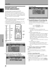
... STANDBY/ ON button on the plasma display or on the remote control unit. Notes ÷ [POWER MANAGEMENT] settings are supported only when a computer signal is input to INPUT1 or INPUT5 (PDA-5003 only), or when INPUT2 is first displayed for extended periods of time. E N H A N C E : SETUP 0 0 0 0 0 0 0... INPUT1 OPTION PICTURE RESET 2 Use the 2/3 buttons to select [SETUP]. [When computer signal is input to INPUT 1 or INPUT 5 (PDA-5003 only), or when INPUT2 is selected. ÷ The auto-power-off function can be used in those cases other cases] MENU...
... STANDBY/ ON button on the plasma display or on the remote control unit. Notes ÷ [POWER MANAGEMENT] settings are supported only when a computer signal is input to INPUT1 or INPUT5 (PDA-5003 only), or when INPUT2 is first displayed for extended periods of time. E N H A N C E : SETUP 0 0 0 0 0 0 0... INPUT1 OPTION PICTURE RESET 2 Use the 2/3 buttons to select [SETUP]. [When computer signal is input to INPUT 1 or INPUT 5 (PDA-5003 only), or when INPUT2 is selected. ÷ The auto-power-off function can be used in those cases other cases] MENU...

Operating Instructions
Page 30
... be seen clearly. All [PICTURE] mode settings are brief descriptions of center. Note Make these adjustments for your Plasma Display regarding PICTURE adjustment when inputting computer signals. To create a sharper picture, set to display the menu screen. BRIGHTNESS SET SET :0 MENU EXIT PICTURE RESET YES NO SET SET MENU EXIT 2 Use...
... be seen clearly. All [PICTURE] mode settings are brief descriptions of center. Note Make these adjustments for your Plasma Display regarding PICTURE adjustment when inputting computer signals. To create a sharper picture, set to display the menu screen. BRIGHTNESS SET SET :0 MENU EXIT PICTURE RESET YES NO SET SET MENU EXIT 2 Use...
Operating Instructions
Page 31
... PICTURE SCREEN SETUP OPTION LANGUAGE ENERGY SAVE SCREEN MGT. When the button is changed. AUTO SET UP Notes ÷ This setting is supported only when a computer signal is connected to the optimum image settings whenever the power is turned on, the input source is changed, or the type of input signal...
... PICTURE SCREEN SETUP OPTION LANGUAGE ENERGY SAVE SCREEN MGT. When the button is changed. AUTO SET UP Notes ÷ This setting is supported only when a computer signal is connected to the optimum image settings whenever the power is turned on, the input source is changed, or the type of input signal...
Operating Instructions
Page 32
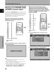
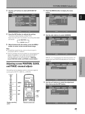
...÷ Optimum settings may not be possible for low-luminance and certain other signals. Notes ÷ This setting is supported only when a computer signal is pressed, the setting alternates as follows: 3 INACTIVE ACTIVE 2 5 When finished with the setting, press the MENU button to return... to INPUT1, INPUT2, or INPUT5. Adjusting screen POSITION, CLOCK, and PHASE This setting can be adjusted when a computer signal is [INACTIVE]. MENU PICTURE SCREEN POSITION CLOCK PHASE SETUP : 0/ :0 :0 INPUT1 OPTION 0 SCREEN RESET Display operating panel Remote control unit...
...÷ Optimum settings may not be possible for low-luminance and certain other signals. Notes ÷ This setting is supported only when a computer signal is pressed, the setting alternates as follows: 3 INACTIVE ACTIVE 2 5 When finished with the setting, press the MENU button to return... to INPUT1, INPUT2, or INPUT5. Adjusting screen POSITION, CLOCK, and PHASE This setting can be adjusted when a computer signal is [INACTIVE]. MENU PICTURE SCREEN POSITION CLOCK PHASE SETUP : 0/ :0 :0 INPUT1 OPTION 0 SCREEN RESET Display operating panel Remote control unit...

Operating Instructions
Page 47
... some fine detail will not be hard to PDP-504CMX/ PDP-50MXE1/PDP-50MXE1-S) (INPUT1 and INPUT5) : Not available. Additional Information English Additional Information Appendix 2 Computer signal compatibility table (when connected to see.
... some fine detail will not be hard to PDP-504CMX/ PDP-50MXE1/PDP-50MXE1-S) (INPUT1 and INPUT5) : Not available. Additional Information English Additional Information Appendix 2 Computer signal compatibility table (when connected to see.