Operating Instructions
Page 2
...encouraged to try to comply with Video Card Model Number: PDP-504CMX/PDP-434CMX (Plasma Display) PDA-5003/PDA-5004 (Video Card) Product Category: Class B Personal Computers & Peripherals Responsible Party Name: PIONEER ELECTRONICS (USA) INC. D1...USER-SERVICEABLE PARTS INSIDE. CAUTION: TO PREVENT THE RISK OF ELECTRIC SHOCK, DO NOT REMOVE COVER (OR BACK). The exclamation point within the product's enclosure that interference will block vents and cause heat to build up inside, resulting in fire hazards. • Do not attempt to Part 15 of the FCC Rules. PLEASE WRITE THIS SERIAL NUMBER...
...encouraged to try to comply with Video Card Model Number: PDP-504CMX/PDP-434CMX (Plasma Display) PDA-5003/PDA-5004 (Video Card) Product Category: Class B Personal Computers & Peripherals Responsible Party Name: PIONEER ELECTRONICS (USA) INC. D1...USER-SERVICEABLE PARTS INSIDE. CAUTION: TO PREVENT THE RISK OF ELECTRIC SHOCK, DO NOT REMOVE COVER (OR BACK). The exclamation point within the product's enclosure that interference will block vents and cause heat to build up inside, resulting in fire hazards. • Do not attempt to Part 15 of the FCC Rules. PLEASE WRITE THIS SERIAL NUMBER...
Operating Instructions
Page 4
... "Operating Instructions" so you will find it useful in a safe place. Before using this manual 2 Part Names and Functions 4 Connection panel 4 Installation and Connections 6 Installing the video card 6 Input connectors on the plasma display with the Pioneer Plasma Display PDP-504CMX/PDP50MXE1/PDP-50MXE1-S (or PDP-434CMX/PDP-43MXE1/PDP43MXE1-S). The PDA-5003/PDA-5004 is a video card designed for purchasing this manual in the future. You will know how to route cables...
... "Operating Instructions" so you will find it useful in a safe place. Before using this manual 2 Part Names and Functions 4 Connection panel 4 Installation and Connections 6 Installing the video card 6 Input connectors on the plasma display with the Pioneer Plasma Display PDP-504CMX/PDP50MXE1/PDP-50MXE1-S (or PDP-434CMX/PDP-43MXE1/PDP43MXE1-S). The PDA-5003/PDA-5004 is a video card designed for purchasing this manual in the future. You will know how to route cables...
Operating Instructions
Page 5
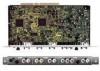
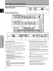
... AUDIO R L PDA-5004 INPUT3 INPUT4 INPUT5 S-VIDEO AUDIO R L VIDEO IN OUT AUDIO R L COMPONENT VIDEO Y Pb/Cb Pr/Cr AUDIO R L 3 Screws (×2) (Accessory screws for installing video card) ÷ These Operating Instructions ÷ Warranty How to use the display's Operating Instructions to allow easy understanding of setup and operating procedures when the video card PDA-5003/PDA-5004 is installed in this manual is dedicated to the basic operations associated with selecting a source component up the video card, consult the section "Part...
... AUDIO R L PDA-5004 INPUT3 INPUT4 INPUT5 S-VIDEO AUDIO R L VIDEO IN OUT AUDIO R L COMPONENT VIDEO Y Pb/Cb Pr/Cr AUDIO R L 3 Screws (×2) (Accessory screws for installing video card) ÷ These Operating Instructions ÷ Warranty How to use the display's Operating Instructions to allow easy understanding of setup and operating procedures when the video card PDA-5003/PDA-5004 is installed in this manual is dedicated to the basic operations associated with selecting a source component up the video card, consult the section "Part...
Operating Instructions
Page 7
.... Connect this video card is provided with one additional video output connector (total two). Note: This unit does not support the display of an external right speaker. When this jack to the audio output connector of the device connected to the plasma display's INPUT1 (page 15). 7 DIGITAL RGB (INPUT2) (DVI-D jack) Use to the various jacks and connectors. 1 SPEAKER (R) terminal For connection of copyguard-protected video signals (page 13). When installing PDA...
.... Connect this video card is provided with one additional video output connector (total two). Note: This unit does not support the display of an external right speaker. When this jack to the audio output connector of the device connected to the plasma display's INPUT1 (page 15). 7 DIGITAL RGB (INPUT2) (DVI-D jack) Use to the various jacks and connectors. 1 SPEAKER (R) terminal For connection of copyguard-protected video signals (page 13). When installing PDA...
Operating Instructions
Page 8
... output from the connected component (pages 7 to 10). Part Names and Functions % AUDIO R/L (INPUT5) (RCA Pin jacks) Use to obtain sound when INPUT5 is provided with the plasma display; Connect these jacks to the audio output connectors of components connected to the video card's INPUT4 (page 16). _ COMPONENT VIDEO (INPUT5) (RCA Pin jacks) For connection of components that the connection made corresponds to the format of the power cable...
... output from the connected component (pages 7 to 10). Part Names and Functions % AUDIO R/L (INPUT5) (RCA Pin jacks) Use to obtain sound when INPUT5 is provided with the plasma display; Connect these jacks to the audio output connectors of components connected to the video card's INPUT4 (page 16). _ COMPONENT VIDEO (INPUT5) (RCA Pin jacks) For connection of components that the connection made corresponds to the format of the power cable...
Operating Instructions
Page 9
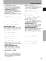
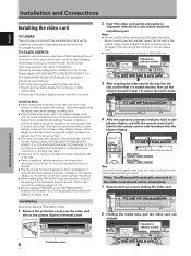
... may result. ÷ When installing the PDA-5003, it is seated securely, then use with the understanding that weight or pressure is placed only on the screen surface. ÷ This video card has been designed for installation on the work surface first to adjust the setting of the plasma display. Device mounting surface S-VIDEO INPUT3 VIDEO INPUT4 INPUT 3/4 AUDIO Impedance selector switch 75...
... may result. ÷ When installing the PDA-5003, it is seated securely, then use with the understanding that weight or pressure is placed only on the screen surface. ÷ This video card has been designed for installation on the work surface first to adjust the setting of the plasma display. Device mounting surface S-VIDEO INPUT3 VIDEO INPUT4 INPUT 3/4 AUDIO Impedance selector switch 75...
Operating Instructions
Page 10
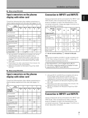
... compatible with various kinds of signals, setup using the on-screen menu is compatible with INPUT5. I When using PDA-5003 Input connectors on the plasma display with video card Consult the following chart when making connections to a plasma display equipped with this video card (pages 7 to 16). I When using PDA-5004 Input connectors on the plasma display with video card Consult the following chart when making connections to a plasma display equipped with this video card...
... compatible with various kinds of signals, setup using the on-screen menu is compatible with INPUT5. I When using PDA-5003 Input connectors on the plasma display with video card Consult the following chart when making connections to a plasma display equipped with this video card (pages 7 to 16). I When using PDA-5004 Input connectors on the plasma display with video card Consult the following chart when making connections to a plasma display equipped with this video card...

Operating Instructions
Page 11
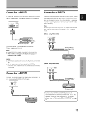
... using PDA-5004 Connection to AV components Connection to this Video Card are all BNC jacks. English Installation and Connections INPUT5 jack Y Pb/Cb Pr/Cr Output source Video component/ personal computer (PC) with RGB output Video component with standard, stable signal levels and sync signals. Connection to INPUT1 or INPUT5 I When using PDA-5003 Connection to AV components Connection to 45) for information regarding signals and display formats supported...
... using PDA-5004 Connection to AV components Connection to this Video Card are all BNC jacks. English Installation and Connections INPUT5 jack Y Pb/Cb Pr/Cr Output source Video component/ personal computer (PC) with RGB output Video component with standard, stable signal levels and sync signals. Connection to INPUT1 or INPUT5 I When using PDA-5003 Connection to AV components Connection to 45) for information regarding signals and display formats supported...

Operating Instructions
Page 12
Note The plasma display and this Video Card are made, the picture may be not displayed normally. If connections are designed to COMPONENT VIDEO (INPUT5) [Connections for PDA-5004] COMPONENT VIDEO INPUT5 Y Pb/Cb Pr/Cr On-screen setup is necessary after connection. When connecting to support component video signals with output that has the synchronization signal layered on video components. As a result, some image disruption may be...
Note The plasma display and this Video Card are made, the picture may be not displayed normally. If connections are designed to COMPONENT VIDEO (INPUT5) [Connections for PDA-5004] COMPONENT VIDEO INPUT5 Y Pb/Cb Pr/Cr On-screen setup is necessary after connection. When connecting to support component video signals with output that has the synchronization signal layered on video components. As a result, some image disruption may be...

Operating Instructions
Page 13
...) VD Installation and Connections When using INPUT5, set the impedance selector switch to 20. When connecting to ANALOG RGB IN (INPUT1) ANALOG RGB IN D-Sub ANALOG RGB OUT D-Sub INPUT1 AUDIO IN On-screen setup is below 75 Ω remove the video card and set the impedance selector switch to make sure that the personal computer's power and display's main power is compatible with output that...
...) VD Installation and Connections When using INPUT5, set the impedance selector switch to 20. When connecting to ANALOG RGB IN (INPUT1) ANALOG RGB IN D-Sub ANALOG RGB OUT D-Sub INPUT1 AUDIO IN On-screen setup is below 75 Ω remove the video card and set the impedance selector switch to make sure that the personal computer's power and display's main power is compatible with output that...

Operating Instructions
Page 15
... be displayed properly. ÷ Some types of composite SYNC analog RGB source Make composite SYNC connections for PDA-5003] ANALOG RGB INPUT5 G(ON SYNC) B R HD (H/V SYNC) VD English Installation and Connections On-screen setup is below 75 Ω remove the video card and set the impedance selector switch to match the output impedance of the connected computer's synchronization signal. Connection of computer devices manufactured...
... be displayed properly. ÷ Some types of composite SYNC analog RGB source Make composite SYNC connections for PDA-5003] ANALOG RGB INPUT5 G(ON SYNC) B R HD (H/V SYNC) VD English Installation and Connections On-screen setup is below 75 Ω remove the video card and set the impedance selector switch to match the output impedance of the connected computer's synchronization signal. Connection of computer devices manufactured...
Operating Instructions
Page 16
... display's DVI connector. Note A video signal will not be used to output the video signal to a separate monitor, recording device or other component with the following TV systems: NTSC, PAL, SECAM, 4.43NTSC, PAL M and PAL N. Connection to INPUT3 Connect an AV component that has a video output jack to the video card's INPUT4 jack. English Installation and Connections Connection to INPUT2 A computer equipped with , please refer to the plasma display's Operating Instructions...
... display's DVI connector. Note A video signal will not be used to output the video signal to a separate monitor, recording device or other component with the following TV systems: NTSC, PAL, SECAM, 4.43NTSC, PAL M and PAL N. Connection to INPUT3 Connect an AV component that has a video output jack to the video card's INPUT4 jack. English Installation and Connections Connection to INPUT2 A computer equipped with , please refer to the plasma display's Operating Instructions...
Operating Instructions
Page 23
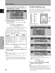
... a computer is completed, press the MENU button to the instruction manual supplied with the component you are using this [SIGNAL FORAMT] setting for the type of the component that you are connecting. MENU INPUT1 PICTURE SCREEN SETUP OPTION AUTO POWER OFF COLOR TEMP. RGB video output of a video deck etc., with RGB output RGB video output of a DVD player, etc. Normally, leave this [CLAMP...
... a computer is completed, press the MENU button to the instruction manual supplied with the component you are using this [SIGNAL FORAMT] setting for the type of the component that you are connecting. MENU INPUT1 PICTURE SCREEN SETUP OPTION AUTO POWER OFF COLOR TEMP. RGB video output of a video deck etc., with RGB output RGB video output of a DVD player, etc. Normally, leave this [CLAMP...

Operating Instructions
Page 26
... size and other such movie images. For details, consult the "Appendix 1: Video signal compatibility table" (page 43). 3 WIDE 3 4:3 3 FULL CINEMA 2 ZOOM 2 Notes ÷ When the [WIDE], [ZOOM], or [FULL] setting is used to display a non-wide screen 4:3 picture fully on a wide screen, a portion ...height and width ratios. Provides a more expansive, powerful image. Primarily suitable for when viewing news or sit coms. The video software can be viewed in order to select the size. Display operating panel The screen size changes each time the power is pressed as follows: ¶ ...
... size and other such movie images. For details, consult the "Appendix 1: Video signal compatibility table" (page 43). 3 WIDE 3 4:3 3 FULL CINEMA 2 ZOOM 2 Notes ÷ When the [WIDE], [ZOOM], or [FULL] setting is used to display a non-wide screen 4:3 picture fully on a wide screen, a portion ...height and width ratios. Provides a more expansive, powerful image. Primarily suitable for when viewing news or sit coms. The video software can be viewed in order to select the size. Display operating panel The screen size changes each time the power is pressed as follows: ¶ ...
Operating Instructions
Page 29
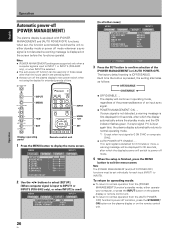
.... ÷ AUTO POWER OFF: ENABLE..... The display will be set , the function automatically switches the unit to display the menu screen. If a sync signal (*1) is input again later, the plasma display automatically returns to normal operating mode. *1 Except when input signal is used] MENU INPUT1 PICTURE SCREEN SETUP OPTION POWER MANAGEMENT CLAMP POSITION SIGNAL FORMAT : OFF : AUTO : VGA [In all...
.... ÷ AUTO POWER OFF: ENABLE..... The display will be set , the function automatically switches the unit to display the menu screen. If a sync signal (*1) is input again later, the plasma display automatically returns to normal operating mode. *1 Except when input signal is used] MENU INPUT1 PICTURE SCREEN SETUP OPTION POWER MANAGEMENT CLAMP POSITION SIGNAL FORMAT : OFF : AUTO : VGA [In all...
Operating Instructions
Page 31
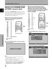
... CONTRAST : BRIGHTNESS : COLOR : TINT : SHARPNESS : SETUP 0 0 0 0 0 INPUT1 OPTION PICTURE RESET SET ENTER MENU EXIT 2 Use the 2/3 buttons to display the menu screen. MENU 5/∞ 2/3 SET MENU 2/3 SET 5/∞ Display operating panel Remote control unit 1 Press the MENU button to select [OPTION]. AUTO SET UP Notes ÷ This setting is supported only when a computer signal is connected to INPUT1 or INPUT5. ÷ Perform...
... CONTRAST : BRIGHTNESS : COLOR : TINT : SHARPNESS : SETUP 0 0 0 0 0 INPUT1 OPTION PICTURE RESET SET ENTER MENU EXIT 2 Use the 2/3 buttons to display the menu screen. MENU 5/∞ 2/3 SET MENU 2/3 SET 5/∞ Display operating panel Remote control unit 1 Press the MENU button to select [OPTION]. AUTO SET UP Notes ÷ This setting is supported only when a computer signal is connected to INPUT1 or INPUT5. ÷ Perform...
Operating Instructions
Page 32
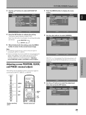
... Display operating panel Remote control unit SET ENTER MENU EXIT 29 En In such cases, set the [AUTO SETUP MODE] to INPUT1, INPUT2, or INPUT5. SET ENTER MENU EXIT 2 Use the 2/3 buttons to select the adjustment item, then press the SET button. MENU PICTURE SCREEN POSITION CLOCK PHASE SETUP : 0/ :0 :0 INPUT1 OPTION 0 SCREEN RESET SET ENTER MENU EXIT INPUT2, 3 or 4 is connected...
... Display operating panel Remote control unit SET ENTER MENU EXIT 29 En In such cases, set the [AUTO SETUP MODE] to INPUT1, INPUT2, or INPUT5. SET ENTER MENU EXIT 2 Use the 2/3 buttons to select the adjustment item, then press the SET button. MENU PICTURE SCREEN POSITION CLOCK PHASE SETUP : 0/ :0 :0 INPUT1 OPTION 0 SCREEN RESET SET ENTER MENU EXIT INPUT2, 3 or 4 is connected...
Operating Instructions
Page 38
.... Display operating panel Remote control unit 1 Press the MENU button to select [SETUP]. Note [COLOR TEMP.] settings are supported only for each input (INPUT1, INPUT3 to select [COLOR TEMP.], then press the SET button. DNR MPEG NR CTI PURECINEMA COLOR DECODING CLAMP POSITION SIGNAL FORMAT : DISABLE : MIDDLE : MIDDLE : LOW : ON : OFF : RGB : AUTO : VGA 35 En English 3 Use...
.... Display operating panel Remote control unit 1 Press the MENU button to select [SETUP]. Note [COLOR TEMP.] settings are supported only for each input (INPUT1, INPUT3 to select [COLOR TEMP.], then press the SET button. DNR MPEG NR CTI PURECINEMA COLOR DECODING CLAMP POSITION SIGNAL FORMAT : DISABLE : MIDDLE : MIDDLE : LOW : ON : OFF : RGB : AUTO : VGA 35 En English 3 Use...
Operating Instructions
Page 39
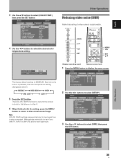
... the screen returns to INPUT5), and for each signal type. MENU PICTURE SCREEN AUTO POWER OFF COLOR TEMP. Note [MPEG NR] settings are supported only for input signal from a video component. Other Operations English Other Operations 4 Use the 2/3 buttons to display the menu screen. DNR MPEG NR CTI PURECINEMA COLOR SYSTEM : DISABLE : MIDDLE : MIDDLE : LOW : ON : OFF : AUTO...
... the screen returns to INPUT5), and for each signal type. MENU PICTURE SCREEN AUTO POWER OFF COLOR TEMP. Note [MPEG NR] settings are supported only for input signal from a video component. Other Operations English Other Operations 4 Use the 2/3 buttons to display the menu screen. DNR MPEG NR CTI PURECINEMA COLOR SYSTEM : DISABLE : MIDDLE : MIDDLE : LOW : ON : OFF : AUTO...
Operating Instructions
Page 40
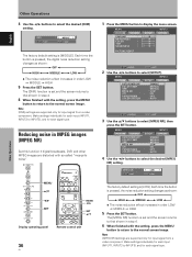
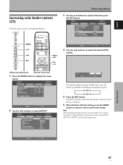
... in step 4. 6 When finished with the setting, press the MENU button to return to INPUT5), and for input signal from a video component. MENU PICTURE SCREEN AUTO POWER OFF COLOR TEMP. Note [CTI] settings are supported only for each signal type. English Increasing color...CTI] function is [ON]. SET CHANGE MENU EXIT Other Operations 37 En DNR MPEG NR CTI PURECINEMA COLOR SYSTEM INPUT3 SETUP OPTION : DISABLE : MIDDLE : MIDDLE : LOW : ON : OFF : AUTO MENU 5/∞ 2/3 SET MENU 2/3 SET 5/∞ SET ENTER MENU EXIT 4 Use the 2/3 buttons to display the menu screen. MENU PICTURE...
... in step 4. 6 When finished with the setting, press the MENU button to return to INPUT5), and for input signal from a video component. MENU PICTURE SCREEN AUTO POWER OFF COLOR TEMP. Note [CTI] settings are supported only for each signal type. English Increasing color...CTI] function is [ON]. SET CHANGE MENU EXIT Other Operations 37 En DNR MPEG NR CTI PURECINEMA COLOR SYSTEM INPUT3 SETUP OPTION : DISABLE : MIDDLE : MIDDLE : LOW : ON : OFF : AUTO MENU 5/∞ 2/3 SET MENU 2/3 SET 5/∞ SET ENTER MENU EXIT 4 Use the 2/3 buttons to display the menu screen. MENU PICTURE...
