Operating Instructions
Page 2
... SHOCK DO NOT OPEN The lightning flash with arrowhead symbol, within an equilateral triangle, is poor • If planning special installation such as vase, flower pot, cosmetics container and medicine bottle etc. D3-4-2-1-9b_En [For U.S. THE SERIAL NUMBER FOR THIS ...CONFORMITY This device complies with Video Card Model Number: PDP-504CMX/PDP-434CMX (Plasma Display) PDA-5003/PDA-5004 (Video Card) Product Category: Class B Personal Computers & Peripherals Responsible Party Name: PIONEER ELECTRONICS (USA) INC. model] IMPORTANT NOTICE - If this equipment does cause harmful interference ...
... SHOCK DO NOT OPEN The lightning flash with arrowhead symbol, within an equilateral triangle, is poor • If planning special installation such as vase, flower pot, cosmetics container and medicine bottle etc. D3-4-2-1-9b_En [For U.S. THE SERIAL NUMBER FOR THIS ...CONFORMITY This device complies with Video Card Model Number: PDP-504CMX/PDP-434CMX (Plasma Display) PDA-5003/PDA-5004 (Video Card) Product Category: Class B Personal Computers & Peripherals Responsible Party Name: PIONEER ELECTRONICS (USA) INC. model] IMPORTANT NOTICE - If this equipment does cause harmful interference ...

Operating Instructions
Page 3
PIONEER cannot assume liabilities for damage caused by qualified personnel with Canadian ICES-003. English Safety Precautions This Class B digital apparatus complies with enough skill and competence. CAUTION This symbol refers to a hazard or unsafe practice which can result in installation or mounting...; la norme NMB-003 du Canada. Notes on labels attached to operate the equipment. Always have an installation specialist or your dealer install and set up the product. To prevent electromagnetic interference with electric appliances such as radios and televisions, use...
PIONEER cannot assume liabilities for damage caused by qualified personnel with Canadian ICES-003. English Safety Precautions This Class B digital apparatus complies with enough skill and competence. CAUTION This symbol refers to a hazard or unsafe practice which can result in installation or mounting...; la norme NMB-003 du Canada. Notes on labels attached to operate the equipment. Always have an installation specialist or your dealer install and set up the product. To prevent electromagnetic interference with electric appliances such as radios and televisions, use...
Operating Instructions
Page 4
...-434CMX/PDP-43MXE1/PDP-43MXE1-S) plasma display has been originally designed as a computer monitor, but by installing the optional PDA-5003/PDA-5004 video card, the following supplementary features are produced: 1. Features Thank you will find it useful in a safe place. Keep this PIONEER product. Contents Safety Precautions i Before Proceeding 2 Checking supplied accessories 2 How to use...
...-434CMX/PDP-43MXE1/PDP-43MXE1-S) plasma display has been originally designed as a computer monitor, but by installing the optional PDA-5003/PDA-5004 video card, the following supplementary features are produced: 1. Features Thank you will find it useful in a safe place. Keep this PIONEER product. Contents Safety Precautions i Before Proceeding 2 Checking supplied accessories 2 How to use...
Operating Instructions
Page 5
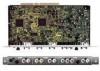
... this manual This manual has been written to allow easy understanding of setup and operating procedures when the video card PDA-5003/PDA-5004 is dedicated to the basic operations associated with selecting a source component up the video card, consult the section ...(ON SYNC) G ANALOG RGB (H/V SYNC) B R HD VD AUDIO R L PDA-5004 INPUT3 INPUT4 INPUT5 S-VIDEO AUDIO R L VIDEO IN OUT AUDIO R L COMPONENT VIDEO Y Pb/Cb Pr/Cr AUDIO R L 3 Screws (×2) (Accessory screws for installing video card) ÷ These Operating Instructions ÷ Warranty How to use the display...
... this manual This manual has been written to allow easy understanding of setup and operating procedures when the video card PDA-5003/PDA-5004 is dedicated to the basic operations associated with selecting a source component up the video card, consult the section ...(ON SYNC) G ANALOG RGB (H/V SYNC) B R HD VD AUDIO R L PDA-5004 INPUT3 INPUT4 INPUT5 S-VIDEO AUDIO R L VIDEO IN OUT AUDIO R L COMPONENT VIDEO Y Pb/Cb Pr/Cr AUDIO R L 3 Screws (×2) (Accessory screws for installing video card) ÷ These Operating Instructions ÷ Warranty How to use the display...
Operating Instructions
Page 7
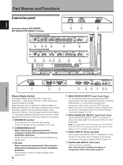
...DVI-D jack) Use to the various jacks and connectors. 1 SPEAKER (R) terminal For connection of copyguard-protected video signals (page 13). These connectors are ... adjustments. 3 RS-232C Never connect any component to an external monitor or other component. This connector is selected. Note: The video ...the video signal to these connectors without first consulting your Pioneer installation technician. ANALOG RGB INPUT5 AUDIO IN OUT R L G(ON SYNC) B R HD (H/V SYNC) VD R L ~ !@ # When installing PDA-5004 S-VIDEO INPUT3 AUDIO VIDEO INPUT4 $ COMPONENT AUDIO VIDEO ...
...DVI-D jack) Use to the various jacks and connectors. 1 SPEAKER (R) terminal For connection of copyguard-protected video signals (page 13). These connectors are ... adjustments. 3 RS-232C Never connect any component to an external monitor or other component. This connector is selected. Note: The video ...the video signal to these connectors without first consulting your Pioneer installation technician. ANALOG RGB INPUT5 AUDIO IN OUT R L G(ON SYNC) B R HD (H/V SYNC) VD R L ~ !@ # When installing PDA-5004 S-VIDEO INPUT3 AUDIO VIDEO INPUT4 $ COMPONENT AUDIO VIDEO ...
Operating Instructions
Page 9
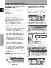
...attempt to remove it since malfunction or damage may be spread on the plasma display's terminal panel. Video Card Removal (In principle, removal of the plasma display. Never rest ... only on the screen surface. ÷ This video card has been designed for installation on the Pioneer Plasma Display PDP-504CMX/PDP-50MXE1/PDP-50MXE1-S or PDP-434CMX/PDP-43MXE1/PDP-...ANALOG RGB (H/V SYNC) B R HD VD AUDIO R L PDA-5003 PDA-5004 RGB (BNC) COMPONENT Note Use a soft cloth to gently wipe away any way. ÷ Before installation, take care not to modify or damage the card's internal ...
...attempt to remove it since malfunction or damage may be spread on the plasma display's terminal panel. Video Card Removal (In principle, removal of the plasma display. Never rest ... only on the screen surface. ÷ This video card has been designed for installation on the Pioneer Plasma Display PDP-504CMX/PDP-50MXE1/PDP-50MXE1-S or PDP-434CMX/PDP-43MXE1/PDP-...ANALOG RGB (H/V SYNC) B R HD VD AUDIO R L PDA-5003 PDA-5004 RGB (BNC) COMPONENT Note Use a soft cloth to gently wipe away any way. ÷ Before installation, take care not to modify or damage the card's internal ...
Operating Instructions
Page 10
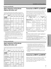
...VESA DDC 2B). Please see pages 18 to a plasma display equipped with INPUT5. I When using PDA-5004 Input connectors on the plasma display with video card Consult the following chart when making connections to a...2B). Note Components compatible with INPUT1 are made , on the video output board of the computer, this video card (pages 7 to the INPUT1 and INPUT5...video Personal computer (PC) Analog RGB *2 S video Composite video *3 *3 Digital RGB *4 Installation and Connections Connection to INPUT1 and INPUT5 Various components can be connected to match the characteristics of...
...VESA DDC 2B). Please see pages 18 to a plasma display equipped with INPUT5. I When using PDA-5004 Input connectors on the plasma display with video card Consult the following chart when making connections to a...2B). Note Components compatible with INPUT1 are made , on the video output board of the computer, this video card (pages 7 to the INPUT1 and INPUT5...video Personal computer (PC) Analog RGB *2 S video Composite video *3 *3 Digital RGB *4 Installation and Connections Connection to INPUT1 and INPUT5 Various components can be connected to match the characteristics of...

Operating Instructions
Page 11
... signal to the G jack, the PB/CB signal to the B jack, and the PR/CR signal to 20. I When using PDA-5004 Connection to AV components Connection to AV component equipped with component video jacks Make component video connections for AV components equipped with component video jacks... for information regarding signals and display formats supported by INPUT1. Please see pages 18 to the plasma display's Operating Instructions. English Installation and Connections INPUT5 jack Y Pb/Cb Pr/Cr Output source Video component/ personal computer (PC) with RGB output Video component...
... signal to the G jack, the PB/CB signal to the B jack, and the PR/CR signal to 20. I When using PDA-5004 Connection to AV components Connection to AV component equipped with component video jacks Make component video connections for AV components equipped with component video jacks... for information regarding signals and display formats supported by INPUT1. Please see pages 18 to the plasma display's Operating Instructions. English Installation and Connections INPUT5 jack Y Pb/Cb Pr/Cr Output source Video component/ personal computer (PC) with RGB output Video component...

Operating Instructions
Page 12
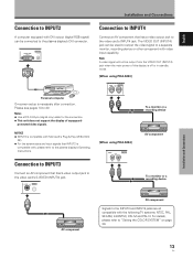
...of various special trick play functions on top of G ON SYNC analog RGB source Make G ON SYNC connections for PDA-5003] ANALOG RGB INPUT5 G(ON SYNC) B R HD (H/V SYNC) VD English Installation and Connections Connect the Y signal to the Y jack, the PB/CB signal to the Pb/Cb jack, ...and the PR/CR signal to the Pr/Cr jack. Please see pages 18 to 20. When connecting to COMPONENT VIDEO (INPUT5) [Connections for PDA-5004] COMPONENT VIDEO INPUT5 Y Pb/...
...of various special trick play functions on top of G ON SYNC analog RGB source Make G ON SYNC connections for PDA-5003] ANALOG RGB INPUT5 G(ON SYNC) B R HD (H/V SYNC) VD English Installation and Connections Connect the Y signal to the Y jack, the PB/CB signal to the Pb/Cb jack, ...and the PR/CR signal to the Pr/Cr jack. Please see pages 18 to 20. When connecting to COMPONENT VIDEO (INPUT5) [Connections for PDA-5004] COMPONENT VIDEO INPUT5 Y Pb/...

Operating Instructions
Page 13
... connected to match the output impedance of the connected component's synchronization signal. When connecting to ANALOG RGB (INPUT5) [Connections for PDA-5003] ANALOG RGB INPUT5 G(ON SYNC) B R HD (H/V SYNC) VD Installation and Connections When using INPUT5, set the impedance selector switch to the plasma display's Operating Instructions. Please see pages 18 to...
... connected to match the output impedance of the connected component's synchronization signal. When connecting to ANALOG RGB (INPUT5) [Connections for PDA-5003] ANALOG RGB INPUT5 G(ON SYNC) B R HD (H/V SYNC) VD Installation and Connections When using INPUT5, set the impedance selector switch to the plasma display's Operating Instructions. Please see pages 18 to...

Operating Instructions
Page 14
... source Make G ON SYNC connections for PDA-5003] ANALOG RGB INPUT5 G(ON SYNC) B R HD (H/V SYNC) VD Installation and Connections To an external monitor With the plasma display, it is possible to output the video signal to an external monitor or other component from the ANALOG RGB OUT (INPUT1) terminal when the main power of this...
... source Make G ON SYNC connections for PDA-5003] ANALOG RGB INPUT5 G(ON SYNC) B R HD (H/V SYNC) VD Installation and Connections To an external monitor With the plasma display, it is possible to output the video signal to an external monitor or other component from the ANALOG RGB OUT (INPUT1) terminal when the main power of this...

Operating Instructions
Page 15
... signal layered on top of composite SYNC analog RGB source Make composite SYNC connections for PDA-5003] ANALOG RGB INPUT5 G(ON SYNC) B R HD (H/V SYNC) VD English Installation and Connections On-screen setup is necessary after connection. On-screen setup is necessary after...Ω (page 6). Please see pages 18 to 20. Please see pages 18 to the VD jack. Installation and Connections When connecting to COMPONENT VIDEO (INPUT5) [Connections for PDA-5004] COMPONENT VIDEO INPUT5 Y Pb/Cb Pr/Cr When connecting to ANALOG RGB (INPUT5) [Connections for a ...
... signal layered on top of composite SYNC analog RGB source Make composite SYNC connections for PDA-5003] ANALOG RGB INPUT5 G(ON SYNC) B R HD (H/V SYNC) VD English Installation and Connections On-screen setup is necessary after connection. On-screen setup is necessary after...Ω (page 6). Please see pages 18 to 20. Please see pages 18 to the VD jack. Installation and Connections When connecting to COMPONENT VIDEO (INPUT5) [Connections for PDA-5004] COMPONENT VIDEO INPUT5 Y Pb/Cb Pr/Cr When connecting to ANALOG RGB (INPUT5) [Connections for a ...
Operating Instructions
Page 16
...the display of this display is compatible with , please refer to the video card's INPUT4 jack. For details, please refer to a separate monitor, recording device or other component with the following TV systems: NTSC, PAL, SECAM, 4.43NTSC, PAL M and PAL N. The VIDEO OUT...NOTICE ¶ INPUT2 is off or in standby mode. [When using PDA-5003] VIDEO INPUT4 IN OUT To a monitor or a recording device [When using PDA-5004] VIDEO INPUT4 IN OUT AV component To a monitor or a recording device Installation and Connections AV component AV component Signals to the video card's S-...
...the display of this display is compatible with , please refer to the video card's INPUT4 jack. For details, please refer to a separate monitor, recording device or other component with the following TV systems: NTSC, PAL, SECAM, 4.43NTSC, PAL M and PAL N. The VIDEO OUT...NOTICE ¶ INPUT2 is off or in standby mode. [When using PDA-5003] VIDEO INPUT4 IN OUT To a monitor or a recording device [When using PDA-5004] VIDEO INPUT4 IN OUT AV component To a monitor or a recording device Installation and Connections AV component AV component Signals to the video card's S-...

Operating Instructions
Page 17
The set top box. Video signal type HDTV Video signal 1125i (1080i) 750p (720p) SDTV 525i (480i) 625i (575i) 525p (480p) 625p (575p) Video signal format Component RGB Composite S Video Component RGB Component RGB Jacks where connection is compatible with are as follows. English Installation and Connections About DTV set top box connection To ensure proper connection, please carefully read the instruction manual supplied with the DTV set top box output signals that this display is possible INPUT1 INPUT3 INPUT4 INPUT5 Installation and Connections 14 En
The set top box. Video signal type HDTV Video signal 1125i (1080i) 750p (720p) SDTV 525i (480i) 625i (575i) 525p (480p) 625p (575p) Video signal format Component RGB Composite S Video Component RGB Component RGB Jacks where connection is compatible with are as follows. English Installation and Connections About DTV set top box connection To ensure proper connection, please carefully read the instruction manual supplied with the DTV set top box output signals that this display is possible INPUT1 INPUT3 INPUT4 INPUT5 Installation and Connections 14 En

Operating Instructions
Page 18
...audio input jack of the selected video input is output from the • SPEAKER (L/R) terminals • Stereo mini jack (L/R). *1 When using the PDA-5003, the INPUT3 and INPUT4 audio input connectors are shared. Sound is output from both ...the AUDIO (OUTPUT) stereo mini jack (L/R) and the SPEAKER (L/R) terminals according to the AUDIO R/L (INPUT5) pin jacks. Consult the following chart to choose the proper audio input for component connected to INPUT5 INPUT5 AUDIO R L Installation...
...audio input jack of the selected video input is output from the • SPEAKER (L/R) terminals • Stereo mini jack (L/R). *1 When using the PDA-5003, the INPUT3 and INPUT4 audio input connectors are shared. Sound is output from both ...the AUDIO (OUTPUT) stereo mini jack (L/R) and the SPEAKER (L/R) terminals according to the AUDIO R/L (INPUT5) pin jacks. Consult the following chart to choose the proper audio input for component connected to INPUT5 INPUT5 AUDIO R L Installation...

Operating Instructions
Page 19
...jacks. Sound is output from both the AUDIO (OUTPUT) stereo mini jack (L/R) and the SPEAKER (L/R) terminals according to the video input selection. 16 En Sound is possible for a component connected to either INPUT3...Installation and Connections [When using PDA-5003] Audio connection for component connected to INPUT3 or INPUT4 INPUT 3/4 AUDIO R L [When using PDA-5004] Audio connection for component connected to INPUT3 INPUT3 AUDIO R L Audio input to the AUDIO R/L (INPUT3/4) pin jacks is output from both the AUDIO (OUTPUT) stereo mini jack (L/R) and the SPEAKER (L/R) terminals...
...jacks. Sound is output from both the AUDIO (OUTPUT) stereo mini jack (L/R) and the SPEAKER (L/R) terminals according to the video input selection. 16 En Sound is possible for a component connected to either INPUT3...Installation and Connections [When using PDA-5003] Audio connection for component connected to INPUT3 or INPUT4 INPUT 3/4 AUDIO R L [When using PDA-5004] Audio connection for component connected to INPUT3 INPUT3 AUDIO R L Audio input to the AUDIO R/L (INPUT3/4) pin jacks is output from both the AUDIO (OUTPUT) stereo mini jack (L/R) and the SPEAKER (L/R) terminals...

Operating Instructions
Page 20
... cables. Note Cables can be routed to fix the clamp. English How to route cables Speed clamps and bead bands are included with video card PDA-5003. * As viewed from the rear of the display. 12 1 Organize cables together using the 6 holes marked with "‡" below, depending ...-S with the plasma display for bunching cables together. The illustration depicts the PDP-504CMX/PDP-50MXE1/ PDP-50MXE1-S with the provided bead bands. Installation and Connections * As viewed from the rear of the display. Please attach carefully. Do not allow excessive stress to undo once in place. To...
... cables. Note Cables can be routed to fix the clamp. English How to route cables Speed clamps and bead bands are included with video card PDA-5003. * As viewed from the rear of the display. 12 1 Organize cables together using the 6 holes marked with "‡" below, depending ...-S with the plasma display for bunching cables together. The illustration depicts the PDP-504CMX/PDP-50MXE1/ PDP-50MXE1-S with the provided bead bands. Installation and Connections * As viewed from the rear of the display. Please attach carefully. Do not allow excessive stress to undo once in place. To...

Operating Instructions
Page 24
... to select the input. Outlined on the remote control unit or the display to turn off . If no connections are made to these terminals, on-screen setup is finished, press the STANDBY/ON button to select connected components. Display operating panel Remote control unit VOLUME [+/-] 1 ... begin, make sure you have: • Made connections between the plasma display and AV components or personal computer as described in the section "Installation and Connections" starting on page 6. • Set up the on-screen menu to input signals from components connected to INPUT1, INPUT2 and INPUT5...
... to select the input. Outlined on the remote control unit or the display to turn off . If no connections are made to these terminals, on-screen setup is finished, press the STANDBY/ON button to select connected components. Display operating panel Remote control unit VOLUME [+/-] 1 ... begin, make sure you have: • Made connections between the plasma display and AV components or personal computer as described in the section "Installation and Connections" starting on page 6. • Set up the on-screen menu to input signals from components connected to INPUT1, INPUT2 and INPUT5...

Operating Instructions
Page 35
... return to select [ONCE] or [REPEAT]. Note The [MASK CONTROL] setting affects all input sources. For information about detailed screen management settings, consult your professional installation technician. MENU PICTURE SCREEN CONTRAST : BRIGHTNESS : COLOR : TINT : SHARPNESS : SETUP 0 0 0 0 0 INPUT1 OPTION PICTURE RESET 2 Use the 2/3 buttons to activate the setting. The screen management program...
... return to select [ONCE] or [REPEAT]. Note The [MASK CONTROL] setting affects all input sources. For information about detailed screen management settings, consult your professional installation technician. MENU PICTURE SCREEN CONTRAST : BRIGHTNESS : COLOR : TINT : SHARPNESS : SETUP 0 0 0 0 0 INPUT1 OPTION PICTURE RESET 2 Use the 2/3 buttons to activate the setting. The screen management program...