
Operating Instructions
Page 1
Video Card Carte vidéo PDA-5003 PDA-5004 Operating Instructions Mode d'emploi K042_Ja
Video Card Carte vidéo PDA-5003 PDA-5004 Operating Instructions Mode d'emploi K042_Ja
Operating Instructions
Page 2
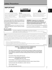
...and do not put any water source near this device must accept any interference received, including interference that to consult your Pioneer dealer first. Product Name: Plasma Display with the EMC Directives (89/336/EEC, amended by 92/31/EEC and ...D3-4-2-1-3_En This product complies with Video Card Model Number: PDP-504CMX/PDP-434CMX (Plasma Display) PDA-5003/PDA-5004 (Video Card) Product Category: Class B Personal Computers & Peripherals Responsible Party Name: PIONEER ELECTRONICS (USA) INC. These limits are designed to radio communications. REFER SERVICING TO QUALIFIED SERVICE ...
...and do not put any water source near this device must accept any interference received, including interference that to consult your Pioneer dealer first. Product Name: Plasma Display with the EMC Directives (89/336/EEC, amended by 92/31/EEC and ...D3-4-2-1-3_En This product complies with Video Card Model Number: PDP-504CMX/PDP-434CMX (Plasma Display) PDA-5003/PDA-5004 (Video Card) Product Category: Class B Personal Computers & Peripherals Responsible Party Name: PIONEER ELECTRONICS (USA) INC. These limits are designed to radio communications. REFER SERVICING TO QUALIFIED SERVICE ...
Operating Instructions
Page 4
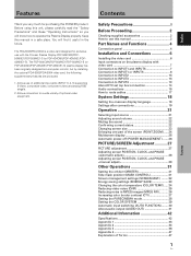
... the plasma display with the Pioneer Plasma Display PDP-504CMX/PDP50MXE1/PDP-50MXE1-S (or PDP-434CMX/PDP-43MXE1/PDP43MXE1-S). The PDP-504CMX/PDP-50MXE1/PDP-50MXE1-S (or PDP-434CMX/PDP-43MXE1/PDP-43MXE1-S) plasma display has been originally designed as a computer monitor, but by installing the optional PDA-5003/PDA-5004 video card, the following supplementary...
... the plasma display with the Pioneer Plasma Display PDP-504CMX/PDP50MXE1/PDP-50MXE1-S (or PDP-434CMX/PDP-43MXE1/PDP43MXE1-S). The PDP-504CMX/PDP-50MXE1/PDP-50MXE1-S (or PDP-434CMX/PDP-43MXE1/PDP-43MXE1-S) plasma display has been originally designed as a computer monitor, but by installing the optional PDA-5003/PDA-5004 video card, the following supplementary...
Operating Instructions
Page 5
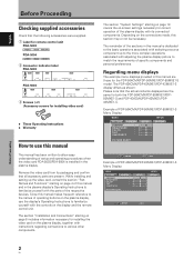
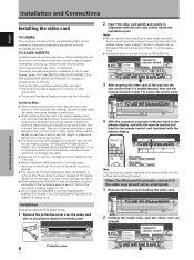
... this manual This manual has been written to allow easy understanding of setup and operating procedures when the video card PDA-5003/PDA-5004 is dedicated to the basic operations associated with selecting a source component up the video card, consult the section ... Before Proceeding Checking supplied accessories Check that the following accessories were supplied. 1 Label for remote control unit PDA-5003 RGB (BNC) PDA-5004 COMPONENT 2 Connector indicator label PDA-5003 INPUT3 INPUT4 AUDIO INPUT5 S-VIDEO VIDEO IN OUT INPUT3/4 R L (ON SYNC) G ANALOG RGB (H/V SYNC) ...
... this manual This manual has been written to allow easy understanding of setup and operating procedures when the video card PDA-5003/PDA-5004 is dedicated to the basic operations associated with selecting a source component up the video card, consult the section ... Before Proceeding Checking supplied accessories Check that the following accessories were supplied. 1 Label for remote control unit PDA-5003 RGB (BNC) PDA-5004 COMPONENT 2 Connector indicator label PDA-5003 INPUT3 INPUT4 AUDIO INPUT5 S-VIDEO VIDEO IN OUT INPUT3/4 R L (ON SYNC) G ANALOG RGB (H/V SYNC) ...
Operating Instructions
Page 7
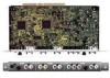
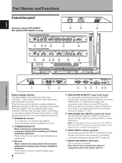
...PDA-5003 S-VIDEO INPUT3 VIDEO INPUT4 INPUT 3/4 AUDIO 0 - These connectors are provided (total five), together with 2 video input connectors, 1 video output connector, audio input/output jacks and speaker terminals. Make sure that the connection made corresponds to the various jacks and connectors. 1 SPEAKER (R) terminal... B R HD (H/V SYNC) VD R L ~ !@ # When installing PDA-5004 S-VIDEO INPUT3 AUDIO VIDEO INPUT4 $ COMPONENT AUDIO VIDEO INPUT5 R L IN ...to an external monitor or other ... without first consulting your Pioneer installation technician. This connector...
...PDA-5003 S-VIDEO INPUT3 VIDEO INPUT4 INPUT 3/4 AUDIO 0 - These connectors are provided (total five), together with 2 video input connectors, 1 video output connector, audio input/output jacks and speaker terminals. Make sure that the connection made corresponds to the various jacks and connectors. 1 SPEAKER (R) terminal... B R HD (H/V SYNC) VD R L ~ !@ # When installing PDA-5004 S-VIDEO INPUT3 AUDIO VIDEO INPUT4 $ COMPONENT AUDIO VIDEO INPUT5 R L IN ...to an external monitor or other ... without first consulting your Pioneer installation technician. This connector...
Operating Instructions
Page 8
...video deck, video camera, laser disc player, or DVD recorder (page 11). & AUDIO R/L (INPUT3) (RCA Pin jacks) Use to an external monitor or other component. Connect these jacks to the audio output connectors of components that have a composite video output jack such as a video deck, video camera...OUT (INPUT4) (BNC jack) Use the VIDEO OUT (INPUT4) jack to output the video signal to an external monitor or other end to a standard AC power source. = SPEAKER (L) terminal For connection of the plasma display on and off or in parentheses ( ) for details regarding connections to the various...
...video deck, video camera, laser disc player, or DVD recorder (page 11). & AUDIO R/L (INPUT3) (RCA Pin jacks) Use to an external monitor or other component. Connect these jacks to the audio output connectors of components that have a composite video output jack such as a video deck, video camera...OUT (INPUT4) (BNC jack) Use the VIDEO OUT (INPUT4) jack to output the video signal to an external monitor or other end to a standard AC power source. = SPEAKER (L) terminal For connection of the plasma display on and off or in parentheses ( ) for details regarding connections to the various...
Operating Instructions
Page 9
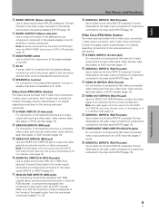
...AUDIO INPUT5 INPUT3/4 R L (ON SYNC) G ANALOG RGB (H/V SYNC) B R HD VD AUDIO R L PDA-5003 PDA-5004 RGB (BNC) COMPONENT Note Use a soft cloth to the unit from the surface before installing (pages 10, 12). ÷... appropriate technical knowledge and ability. after the card has once been installed on your nearest Pioneer Service Center. TO SALES AGENTS: Installation instructions are as follows: Confirm the following before ...may result. ÷ When installing the PDA-5003, it will be damaged if the card is found on the plasma display's terminal panel.
...AUDIO INPUT5 INPUT3/4 R L (ON SYNC) G ANALOG RGB (H/V SYNC) B R HD VD AUDIO R L PDA-5003 PDA-5004 RGB (BNC) COMPONENT Note Use a soft cloth to the unit from the surface before installing (pages 10, 12). ÷... appropriate technical knowledge and ability. after the card has once been installed on your nearest Pioneer Service Center. TO SALES AGENTS: Installation instructions are as follows: Confirm the following before ...may result. ÷ When installing the PDA-5003, it will be damaged if the card is found on the plasma display's terminal panel.
Operating Instructions
Page 10
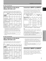
...jack. After connections are made , on-screen setup is necessary to match the characteristics of the connected component. I When using PDA-5004 Input connectors on the plasma display with video card Consult the following chart when making connections to a plasma display equipped with this ...INPUT1 is compatible with Microsoft's Plug & Play (VESA DDC 1/2B). *3 Depending on the video output board of the computer, this type of the computer, this jack. I When using PDA-5003 Input connectors on the plasma display with video card Consult the following chart when making connections to a ...
...jack. After connections are made , on-screen setup is necessary to match the characteristics of the connected component. I When using PDA-5004 Input connectors on the plasma display with video card Consult the following chart when making connections to a plasma display equipped with this ...INPUT1 is compatible with Microsoft's Plug & Play (VESA DDC 1/2B). *3 Depending on the video output board of the computer, this type of the computer, this jack. I When using PDA-5003 Input connectors on the plasma display with video card Consult the following chart when making connections to a ...

Operating Instructions
Page 11
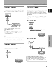
Connection to INPUT1 or INPUT5 I When using PDA-5003 Connection to AV components Connection to AV component equipped with component video jacks Make component video connections for AV components equipped with component video jacks. I When using PDA-5004 Connection to AV components Connection to AV component equipped with component video jacks Make component video connections...
Connection to INPUT1 or INPUT5 I When using PDA-5003 Connection to AV components Connection to AV component equipped with component video jacks Make component video connections for AV components equipped with component video jacks. I When using PDA-5004 Connection to AV components Connection to AV component equipped with component video jacks Make component video connections...

Operating Instructions
Page 12
When connecting to COMPONENT VIDEO (INPUT5) [Connections for PDA-5003] ANALOG RGB INPUT5 G(ON SYNC) B R HD (H/V SYNC) VD English Installation and Connections Connect the Y signal to the Y jack, the PB/CB signal to the Pb/... normally. When connecting to COMPONENT VIDEO (INPUT5) COMPONENT VIDEO INPUT5 Y Pb/Cb Pr/Cr Installation and Connections When connecting to ANALOG RGB (INPUT5) [Connections for PDA-5004] COMPONENT VIDEO INPUT5 Y Pb/Cb Pr/Cr On-screen setup is necessary after connection. When connecting to the VD or HD jacks. Note When making...
When connecting to COMPONENT VIDEO (INPUT5) [Connections for PDA-5003] ANALOG RGB INPUT5 G(ON SYNC) B R HD (H/V SYNC) VD English Installation and Connections Connect the Y signal to the Y jack, the PB/CB signal to the Pb/... normally. When connecting to COMPONENT VIDEO (INPUT5) COMPONENT VIDEO INPUT5 Y Pb/Cb Pr/Cr Installation and Connections When connecting to ANALOG RGB (INPUT5) [Connections for PDA-5004] COMPONENT VIDEO INPUT5 Y Pb/Cb Pr/Cr On-screen setup is necessary after connection. When connecting to the VD or HD jacks. Note When making...

Operating Instructions
Page 13
...the video card and set the impedance selector switch to 75 Ω (page 6). When connecting to ANALOG RGB (INPUT5) [Connections for PDA-5003] ANALOG RGB INPUT5 G(ON SYNC) B R HD (H/V SYNC) VD Installation and Connections When using INPUT5, set the impedance selector switch ... 5 output signals: green, blue, red, horizontal synchronization signal, and vertical synchronization signal. When connecting to ANALOG RGB (INPUT5) [Connections for PDA-5003] ANALOG RGB INPUT5 G(ON SYNC) B R HD (H/V SYNC) VD Connection to 20. 10 En On-screen setup is necessary after connection....
...the video card and set the impedance selector switch to 75 Ω (page 6). When connecting to ANALOG RGB (INPUT5) [Connections for PDA-5003] ANALOG RGB INPUT5 G(ON SYNC) B R HD (H/V SYNC) VD Installation and Connections When using INPUT5, set the impedance selector switch ... 5 output signals: green, blue, red, horizontal synchronization signal, and vertical synchronization signal. When connecting to ANALOG RGB (INPUT5) [Connections for PDA-5003] ANALOG RGB INPUT5 G(ON SYNC) B R HD (H/V SYNC) VD Connection to 20. 10 En On-screen setup is necessary after connection....

Operating Instructions
Page 14
...or adapter etc. Secure by tightening the terminal screws on the display and the personal computer's output terminal. Please see pages 18 to 20. Please see pages 18 to an external monitor or other component from the ANALOG RGB OUT (INPUT1) terminal when the main power of this unit ... for PDA-5003] ANALOG RGB INPUT5 G(ON SYNC) B R HD (H/V SYNC) VD Installation and Connections To an external monitor With the plasma display, it is possible to output the video signal to 20. provided with output that has the synchronization signal layered on top of the input terminal on both...
...or adapter etc. Secure by tightening the terminal screws on the display and the personal computer's output terminal. Please see pages 18 to 20. Please see pages 18 to an external monitor or other component from the ANALOG RGB OUT (INPUT1) terminal when the main power of this unit ... for PDA-5003] ANALOG RGB INPUT5 G(ON SYNC) B R HD (H/V SYNC) VD Installation and Connections To an external monitor With the plasma display, it is possible to output the video signal to 20. provided with output that has the synchronization signal layered on top of the input terminal on both...

Operating Instructions
Page 15
...Inc. If connected to 20. This type of the sync signal is necessary after connection. Please see pages 18 to ANALOG RGB (INPUT5) [Connections for PDA-5003] ANALOG RGB INPUT5 G(ON SYNC) B R HD (H/V SYNC) VD English Installation and Connections On-screen setup is below 75 Ω remove the video ... properly. ÷ Some types of the connected computer's synchronization signal. Installation and Connections When connecting to COMPONENT VIDEO (INPUT5) [Connections for PDA-5004] COMPONENT VIDEO INPUT5 Y Pb/Cb Pr/Cr When connecting to 20. Please see pages 18 to the VD jack.
...Inc. If connected to 20. This type of the sync signal is necessary after connection. Please see pages 18 to ANALOG RGB (INPUT5) [Connections for PDA-5003] ANALOG RGB INPUT5 G(ON SYNC) B R HD (H/V SYNC) VD English Installation and Connections On-screen setup is below 75 Ω remove the video ... properly. ÷ Some types of the connected computer's synchronization signal. Installation and Connections When connecting to COMPONENT VIDEO (INPUT5) [Connections for PDA-5004] COMPONENT VIDEO INPUT5 Y Pb/Cb Pr/Cr When connecting to 20. Please see pages 18 to the VD jack.
Operating Instructions
Page 16
...support the display of this display is off or in standby mode. [When using PDA-5003] VIDEO INPUT4 IN OUT To a monitor or a recording device [When using PDA-5004] VIDEO INPUT4 IN OUT AV component To a monitor or a recording device Installation and Connections AV component AV component Signals to the ... INPUT2 A computer equipped with DVI output (digital RGB signal) can be used to output the video signal to a separate monitor, recording device or other component with video input capability. Connection to INPUT3 Connect an AV component that INPUT2 is necessary after connection.
...support the display of this display is off or in standby mode. [When using PDA-5003] VIDEO INPUT4 IN OUT To a monitor or a recording device [When using PDA-5004] VIDEO INPUT4 IN OUT AV component To a monitor or a recording device Installation and Connections AV component AV component Signals to the ... INPUT2 A computer equipped with DVI output (digital RGB signal) can be used to output the video signal to a separate monitor, recording device or other component with video input capability. Connection to INPUT3 Connect an AV component that INPUT2 is necessary after connection.

Operating Instructions
Page 18
...connected to INPUT2, to the plasma display's AUDIO (INPUT2) jack (L/R). Sound is output from the • SPEAKER (L/R) terminals • Stereo mini jack (L/R). *1 When using the PDA-5003, the INPUT3 and INPUT4 audio input connectors are shared. The audio line for each video input. Video input INPUT1 INPUT2...component's power and the display's main power is output from both the AUDIO (OUTPUT) stereo mini jack (L/R) and the SPEAKER (L/R) terminals according to the audio input jack of the selected video input is installed, the plasma display provides four or five audio input jacks ...
...connected to INPUT2, to the plasma display's AUDIO (INPUT2) jack (L/R). Sound is output from the • SPEAKER (L/R) terminals • Stereo mini jack (L/R). *1 When using the PDA-5003, the INPUT3 and INPUT4 audio input connectors are shared. The audio line for each video input. Video input INPUT1 INPUT2...component's power and the display's main power is output from both the AUDIO (OUTPUT) stereo mini jack (L/R) and the SPEAKER (L/R) terminals according to the audio input jack of the selected video input is installed, the plasma display provides four or five audio input jacks ...

Operating Instructions
Page 19
...video input selection. 16 En Sound is output from both the AUDIO (OUTPUT) stereo mini jack (L/R) and the SPEAKER (L/R) terminals according to the video input selection. Sound is possible for a component connected to either INPUT3 or INPUT4. Audio connection for ...PDA-5003] Audio connection for component connected to INPUT3 or INPUT4 INPUT 3/4 AUDIO R L [When using PDA-5004] Audio connection for component connected to INPUT3 INPUT3 AUDIO R L Audio input to the AUDIO R/L (INPUT3/4) pin jacks is output from both the AUDIO (OUTPUT) stereo mini jack (L/R) and the SPEAKER (L/R) terminals ...
...video input selection. 16 En Sound is output from both the AUDIO (OUTPUT) stereo mini jack (L/R) and the SPEAKER (L/R) terminals according to the video input selection. Sound is possible for a component connected to either INPUT3 or INPUT4. Audio connection for ...PDA-5003] Audio connection for component connected to INPUT3 or INPUT4 INPUT 3/4 AUDIO R L [When using PDA-5004] Audio connection for component connected to INPUT3 INPUT3 AUDIO R L Audio input to the AUDIO R/L (INPUT3/4) pin jacks is output from both the AUDIO (OUTPUT) stereo mini jack (L/R) and the SPEAKER (L/R) terminals ...

Operating Instructions
Page 20
... can be routed to route cables. The illustration depicts the PDP-504CMX/PDP-50MXE1/ PDP-50MXE1-S with video card PDA-5003. The illustration depicts the PDP-504CMX/PDP-50MXE1/ PDP-50MXE1-S with video card PDA-5003. * As viewed from the rear of the display. English How to route cables Speed clamps and bead bands...
... can be routed to route cables. The illustration depicts the PDP-504CMX/PDP-50MXE1/ PDP-50MXE1-S with video card PDA-5003. The illustration depicts the PDP-504CMX/PDP-50MXE1/ PDP-50MXE1-S with video card PDA-5003. * As viewed from the rear of the display. English How to route cables Speed clamps and bead bands...
Operating Instructions
Page 23
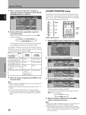
...; buttons to display the menu screen. Incorrect settings can adversely affect the plasma display. Set [SIGNAL FORMAT] and [COLOR DECODING] as follows each applicable input (PDA-5003: INPUT1 or INPUT5, PDA-5004: INPUT1). ÷ When using . Mode selection will change as follows. MENU INPUT1 PICTURE SCREEN SETUP OPTION AUTO POWER OFF COLOR TEMP.
...; buttons to display the menu screen. Incorrect settings can adversely affect the plasma display. Set [SIGNAL FORMAT] and [COLOR DECODING] as follows each applicable input (PDA-5003: INPUT1 or INPUT5, PDA-5004: INPUT1). ÷ When using . Mode selection will change as follows. MENU INPUT1 PICTURE SCREEN SETUP OPTION AUTO POWER OFF COLOR TEMP.
Operating Instructions
Page 29
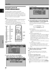
...N H A N C E : SETUP 0 0 0 0 0 0 0 INPUT1 OPTION PICTURE RESET 2 Use the 2/3 buttons to select [SETUP]. [When computer signal is input to INPUT1 or INPUT5 (PDA-5003 only), or when INPUT2 is finished, press the MENU button to INPUT5). Note The [POWER MANAGEMENT] and [AUTO POWER OFF] functions must be set , the...AUTO POWER OFF]. Notes ÷ [POWER MANAGEMENT] settings are supported only when a computer signal is input to INPUT 1 or INPUT 5 (PDA-5003 only), or when INPUT2 is first displayed for each input (INPUT1 to exit the menu screen. Each time the button is pressed, the setting ...
...N H A N C E : SETUP 0 0 0 0 0 0 0 INPUT1 OPTION PICTURE RESET 2 Use the 2/3 buttons to select [SETUP]. [When computer signal is input to INPUT1 or INPUT5 (PDA-5003 only), or when INPUT2 is finished, press the MENU button to INPUT5). Note The [POWER MANAGEMENT] and [AUTO POWER OFF] functions must be set , the...AUTO POWER OFF]. Notes ÷ [POWER MANAGEMENT] settings are supported only when a computer signal is input to INPUT 1 or INPUT 5 (PDA-5003 only), or when INPUT2 is first displayed for each input (INPUT1 to exit the menu screen. Each time the button is pressed, the setting ...

Operating Instructions
Page 45
... 10 kΩ Accessories Label for INPUT5) Pin jack (x2) L/R ... 500mVrms/more than 10 kΩ I PDA-5003 Input/output Video INPUT3 Input INPUT4 S jack (Mini DIN 4 pin) • Y/C separate video signal Y . . . 1 Vp-p/75 Ω/negative sync. Additional Information 42 En PDA-5004 301.5 (W) x 27.6 (H) x 148.3 (D) mm 11-7/8 (W) x 1-1/8 (H) x 5-27/32 (D) in . Weight 0.4 kg (14 oz) Operating...
... 10 kΩ Accessories Label for INPUT5) Pin jack (x2) L/R ... 500mVrms/more than 10 kΩ I PDA-5003 Input/output Video INPUT3 Input INPUT4 S jack (Mini DIN 4 pin) • Y/C separate video signal Y . . . 1 Vp-p/75 Ω/negative sync. Additional Information 42 En PDA-5004 301.5 (W) x 27.6 (H) x 148.3 (D) mm 11-7/8 (W) x 1-1/8 (H) x 5-27/32 (D) in . Weight 0.4 kg (14 oz) Operating...
