Service Manual
Page 1
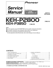
... Belgium PIONEER ELECTRONICS ASIACENTRE PTE.LTD. 253 Alexandra Road, #04-01, Singapore 159936 C PIONEER ELECTRONIC CORPORATION 1998 K-ZZB. Service KEH-P2800/X1M/UC Manual ORDER NO. SCHEMATIC DIAGRAM 8 4. See the separate manual CX-644(CRT1800) for the cassette mechanism ...description. - ELECTRICAL PARTS LIST 26 6. GENERAL INFORMATION 34 7.1 PARTS 34 7.1.1 IC 34 7.1.2 DISPLAY 38 7.2 DISASSEMBLY 39 7.3 BLOCK DIAGRAM 40 8. SAFETY INFORMATION 2 2. DEC. 1998 Printed in Japan CRT2268 MULTI-CD CONTROL HIGH POWER CASSETTE PLAYER WITH FM/AM TUNER KEH-P2800 KEH...
... Belgium PIONEER ELECTRONICS ASIACENTRE PTE.LTD. 253 Alexandra Road, #04-01, Singapore 159936 C PIONEER ELECTRONIC CORPORATION 1998 K-ZZB. Service KEH-P2800/X1M/UC Manual ORDER NO. SCHEMATIC DIAGRAM 8 4. See the separate manual CX-644(CRT1800) for the cassette mechanism ...description. - ELECTRICAL PARTS LIST 26 6. GENERAL INFORMATION 34 7.1 PARTS 34 7.1.1 IC 34 7.1.2 DISPLAY 38 7.2 DISASSEMBLY 39 7.3 BLOCK DIAGRAM 40 8. SAFETY INFORMATION 2 2. DEC. 1998 Printed in Japan CRT2268 MULTI-CD CONTROL HIGH POWER CASSETTE PLAYER WITH FM/AM TUNER KEH-P2800 KEH...
Service Manual
Page 8
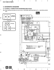
SCHEMATIC DIAGRAM 3.1 OVERALL CONNECTION DIAGRAM(GUIDE PAGE) A Note: When ordering service parts, be sure to refer to "EXPLODED VIEWS AND PARTS LIST" or "ELECTRICAL PARTS LIST". 1 2 3 4 KEH-P2800,P3850 3. A-a Large size A-a A-b SCH diagram B FM/AM TUNER UNIT CWE1467(/UC) CWE1486(/ES) A-a A-b Guide page B A-a A-b Detailed page 220 C D CASSETTE 24dBs PCB D 8 AD 1 2 3 4
SCHEMATIC DIAGRAM 3.1 OVERALL CONNECTION DIAGRAM(GUIDE PAGE) A Note: When ordering service parts, be sure to refer to "EXPLODED VIEWS AND PARTS LIST" or "ELECTRICAL PARTS LIST". 1 2 3 4 KEH-P2800,P3850 3. A-a Large size A-a A-b SCH diagram B FM/AM TUNER UNIT CWE1467(/UC) CWE1486(/ES) A-a A-b Guide page B A-a A-b Detailed page 220 C D CASSETTE 24dBs PCB D 8 AD 1 2 3 4
Service Manual
Page 18
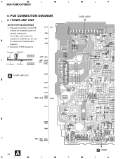
1 2 KEH-P2800,P3850 4. For further information for several destination. Viewpoint of PCB diagrams Connector Capacitor SIDE A B P.C.Board Chip Part SIDE B A TUNER AMP UNIT 3 4 CORD ASSY C D A 18 C CN901 1 2 3 4 The parts mounted on this PCB include all necessary parts for respective destinations, be sure to check with the schematic diagram. 2. PCB CONNECTION DIAGRAM A 4.1 TUNER AMP UNIT NOTE FOR PCB DIAGRAMS 1.
1 2 KEH-P2800,P3850 4. For further information for several destination. Viewpoint of PCB diagrams Connector Capacitor SIDE A B P.C.Board Chip Part SIDE B A TUNER AMP UNIT 3 4 CORD ASSY C D A 18 C CN901 1 2 3 4 The parts mounted on this PCB include all necessary parts for respective destinations, be sure to check with the schematic diagram. 2. PCB CONNECTION DIAGRAM A 4.1 TUNER AMP UNIT NOTE FOR PCB DIAGRAMS 1.
Service Manual
Page 32
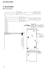
KEH-P2800,P3850 6. ADJUSTMENT - Connection Diagram TUNER AMP UNIT BACK UP ACC GND Lch + Lch - 4Ω Rch + Rch - 4Ω +14.4V DC Regulated GND P o w e r S u p p l y mV Meter (1) Oscilloscope Antenna Dummy Antenna 50Ω(37.5Ω) FM SSG 50Ω(75Ω) Stereo Modulator FM/AM TUNER UNIT (TOP VIEW) L2 Pin26 Antenna L4 T31 Pin 19 DC V Pin14 Meter(1) L5 Pin13 FM/AM TUNER UNIT VR154 T51 Pin1 FM/AM TUNER UNIT (BOTTOM VIEW) T51 Center Meter C63 32
KEH-P2800,P3850 6. ADJUSTMENT - Connection Diagram TUNER AMP UNIT BACK UP ACC GND Lch + Lch - 4Ω Rch + Rch - 4Ω +14.4V DC Regulated GND P o w e r S u p p l y mV Meter (1) Oscilloscope Antenna Dummy Antenna 50Ω(37.5Ω) FM SSG 50Ω(75Ω) Stereo Modulator FM/AM TUNER UNIT (TOP VIEW) L2 Pin26 Antenna L4 T31 Pin 19 DC V Pin14 Meter(1) L5 Pin13 FM/AM TUNER UNIT VR154 T51 Pin1 FM/AM TUNER UNIT (BOTTOM VIEW) T51 Center Meter C63 32
Service Manual
Page 41
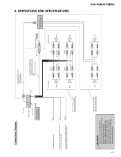
... ≠ + Rear ≠ 41 Black To electric terminal controlled by ignition switch (12 V DC) ON/OFF. OPERATIONS AND SPECIFICATIONS Connection Diagram This Unit Rear output Antenna jack Multi-CD player (sold separately) KEH-P2800,P3850 CAUTION • Cords for this unit to another unit, refer to the 2 speakers in the front or the rear. 8.
... ≠ + Rear ≠ 41 Black To electric terminal controlled by ignition switch (12 V DC) ON/OFF. OPERATIONS AND SPECIFICATIONS Connection Diagram This Unit Rear output Antenna jack Multi-CD player (sold separately) KEH-P2800,P3850 CAUTION • Cords for this unit to another unit, refer to the 2 speakers in the front or the rear. 8.


