Owner's Manual
Page 2
... NO USER-SERVICEABLE PARTS COMPARTMENT WARNING IS LOCATED ON THE APPLIANCE BOTTOM. D8-10-2_En 1) Read these instructions. 2) Keep these operating instructions so you have fallen into an outlet on vacation). IMPORTANT NOTICE - Install in the cabinet are designed to operate your model properly. The wide blade or the third prong are wet as power-supply cord or plug is the same. Servicing is...
... NO USER-SERVICEABLE PARTS COMPARTMENT WARNING IS LOCATED ON THE APPLIANCE BOTTOM. D8-10-2_En 1) Read these instructions. 2) Keep these operating instructions so you have fallen into an outlet on vacation). IMPORTANT NOTICE - Install in the cabinet are designed to operate your model properly. The wide blade or the third prong are wet as power-supply cord or plug is the same. Servicing is...
Owner's Manual
Page 3
... AND HEADPHONES 8 CONNECTING THE POWER CORD 8 NAMES AND FUNCTIONS OF PARTS 9 MIXER OPERATIONS 13 FADER START FUNCTION 14 EFFECT FUNCTIONS 16 PRODUCING BEAT EFFECTS 18 MANUAL FILTER OPERATION 19 EFFECT FREQUENCY FILTER OPERATION 19 EFFECT PARAMETERS 20 MIDI SETTINGS 21 SYNCHRONIZING AUDIO SIGNALS TO EXTERNAL SEQUENCER, OR USING DJM-700-S/DJM-700-K INFORMATION TO OPERATE AN EXTERNAL SEQUENCER 21 MIDI MESSAGES 22 PROGRAM CHANGE 24 SNAPSHOT 24 MIDI ON/OFF 24 TROUBLESHOOTING 25 SPECIFICATIONS 26 BLOCK DIAGRAM 27 3 En Now it's time to excessive noise. One that the power supply...
... AND HEADPHONES 8 CONNECTING THE POWER CORD 8 NAMES AND FUNCTIONS OF PARTS 9 MIXER OPERATIONS 13 FADER START FUNCTION 14 EFFECT FUNCTIONS 16 PRODUCING BEAT EFFECTS 18 MANUAL FILTER OPERATION 19 EFFECT FREQUENCY FILTER OPERATION 19 EFFECT PARAMETERS 20 MIDI SETTINGS 21 SYNCHRONIZING AUDIO SIGNALS TO EXTERNAL SEQUENCER, OR USING DJM-700-S/DJM-700-K INFORMATION TO OPERATE AN EXTERNAL SEQUENCER 21 MIDI MESSAGES 22 PROGRAM CHANGE 24 SNAPSHOT 24 MIDI ON/OFF 24 TROUBLESHOOTING 25 SPECIFICATIONS 26 BLOCK DIAGRAM 27 3 En Now it's time to excessive noise. One that the power supply...
Owner's Manual
Page 4
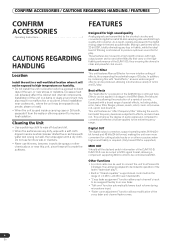
... to operation of filtering is performed with a dry cloth. Manual Filter This unit features Manual Effecter for more convenient for cutting studio tracks or on the DJM-600 are subjected to the entire frequency range. This enhances the degree of special effects, including delay, echo, trans, filter, flanger, phaser, reverb, robot, crush, roll, reverse roll, uproll, and downroll. Other functions • A control cable can be linked to direct rays...
... to operation of filtering is performed with a dry cloth. Manual Filter This unit features Manual Effecter for more convenient for cutting studio tracks or on the DJM-600 are subjected to the entire frequency range. This enhances the degree of special effects, including delay, echo, trans, filter, flanger, phaser, reverb, robot, crush, roll, reverse roll, uproll, and downroll. Other functions • A control cable can be linked to direct rays...
Owner's Manual
Page 5
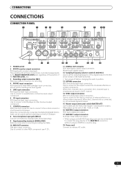
... CD player. 8 Two microphone input jacks (MIC 2) Connect microphones equipped with phone-type plugs. 9 Signal grounding terminals (SIGNAL GND) Reduces noise when connecting an analog turntable. 10 MIDI OUT connector DIN type output connector. When the connectors are recommended to connect the plug directly to the MASTER 2 connectors without using a cord with RCA-type plug, users are connected, the DJM-700-S/DJM-700-K's fader can be used to connect a cassette deck or other similar components. Use to connect to the R channel. 14 SEND output connectors...
... CD player. 8 Two microphone input jacks (MIC 2) Connect microphones equipped with phone-type plugs. 9 Signal grounding terminals (SIGNAL GND) Reduces noise when connecting an analog turntable. 10 MIDI OUT connector DIN type output connector. When the connectors are recommended to connect the plug directly to the MASTER 2 connectors without using a cord with RCA-type plug, users are connected, the DJM-700-S/DJM-700-K's fader can be used to connect a cassette deck or other similar components. Use to connect to the R channel. 14 SEND output connectors...
Owner's Manual
Page 6
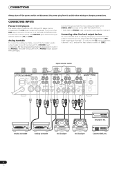
...-4 PHONO LINE L CH-3 PHONO LINE L CH-2 PHONO CD L CH-1 LINE CD L CONTROL CONTROL MIC 2 R MASTER2 MASTER RL ATT. -6dB -3dB 0dB R SIGNAL GND SEND R L(MONO) R R RETURN R L(MONO) DIGITAL OUT fs(Hz) 48k 96k MIDI OUT CD player, etc. Connecting other line level output devices To use a cassette deck or ordinary CD player, connect its outlet when making or changing connections. Connect the ground wire from its audio output connectors to 4 PHONO input connectors. CONNECTING INPUTS Pioneer DJ CD players The audio output connectors...
...-4 PHONO LINE L CH-3 PHONO LINE L CH-2 PHONO CD L CH-1 LINE CD L CONTROL CONTROL MIC 2 R MASTER2 MASTER RL ATT. -6dB -3dB 0dB R SIGNAL GND SEND R L(MONO) R R RETURN R L(MONO) DIGITAL OUT fs(Hz) 48k 96k MIDI OUT CD player, etc. Connecting other line level output devices To use a cassette deck or ordinary CD player, connect its outlet when making or changing connections. Connect the ground wire from its audio output connectors to 4 PHONO input connectors. CONNECTING INPUTS Pioneer DJ CD players The audio output connectors...
Owner's Manual
Page 7
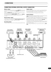
...MONO/STEREO switch is furnished with monaural inputs, connect only to the output connectors of the power amplifier used. Recording output These are output connectors for booth monitor) Cassette deck (analog input recording device) Power amplifier (RCA plug input connectors) Digital input AV amplifier (digital input recording device) Sampling frequency selector switch POWER OFF ON BOOTH REC L 1 GND 2 HOT R 3 COLD R MASTER1 L CH-4 PHONO LINE L CH-3 PHONO LINE L CH-2 PHONO CD L CH-1 LINE CD L CONTROL CONTROL MIC 2 R MASTER2 MASTER RL ATT. -6dB -3dB 0dB R SIGNAL GND SEND...
...MONO/STEREO switch is furnished with monaural inputs, connect only to the output connectors of the power amplifier used. Recording output These are output connectors for booth monitor) Cassette deck (analog input recording device) Power amplifier (RCA plug input connectors) Digital input AV amplifier (digital input recording device) Sampling frequency selector switch POWER OFF ON BOOTH REC L 1 GND 2 HOT R 3 COLD R MASTER1 L CH-4 PHONO LINE L CH-3 PHONO LINE L CH-2 PHONO CD L CH-1 LINE CD L CONTROL CONTROL MIC 2 R MASTER2 MASTER RL ATT. -6dB -3dB 0dB R SIGNAL GND SEND...
Owner's Manual
Page 8
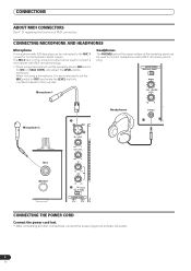
...;6.3 mm stereo phone plug. HI - - - -12 +12 - Headphones The PHONES jack on the upper surface of MIDI connectors. HEADPHONES MONO SPLIT STEREO MIXING Microphone 1 CUE MASTER LEVEL Headphones 0 PHONES Microphone 2 MIC 2 MIDI OUT MIC1 MIC1 LEVEL OV 1 0 7 MIC2 LEVEL 4 2 1 0 0 - CONNECTING MICROPHONE AND HEADPHONES Microphone A microphone with XLR-type plug can be used to connect headphones with Ø6.3 mm phone plugs. • When using a microphone, it is recommended to set the operating panel's MIC switch to [ON] or [TALK OVER], and adjust the LEVEL dial as...
...;6.3 mm stereo phone plug. HI - - - -12 +12 - Headphones The PHONES jack on the upper surface of MIDI connectors. HEADPHONES MONO SPLIT STEREO MIXING Microphone 1 CUE MASTER LEVEL Headphones 0 PHONES Microphone 2 MIC 2 MIDI OUT MIC1 MIC1 LEVEL OV 1 0 7 MIC2 LEVEL 4 2 1 0 0 - CONNECTING MICROPHONE AND HEADPHONES Microphone A microphone with XLR-type plug can be used to connect headphones with Ø6.3 mm phone plugs. • When using a microphone, it is recommended to set the operating panel's MIC switch to [ON] or [TALK OVER], and adjust the LEVEL dial as...
Owner's Manual
Page 9
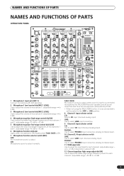
... FADER ASSIGN 22 A B BALANCE REVERB 25 PHASER FLANGER FILTER TRANS ECHO ROBOT CRUSH ROLL ROLL REVERSE UP DOWN L R MONO STEREO 26 DELAY 4 3 2 1 39 SND/RTN MIC CF.A CF.B 40 MASTER BOOTH MONITOR LEVEL 27 TIME 0 CH FADER 20 CROSS FADER 21 41 LEVEL/DEPTH MIN MAX ON/OFF 42 43 1 Microphone 1 input jack (MIC 1) Connect microphone with XLR-type plug. 2 Microphone 1 level control dial (MIC 1 LEVEL) Use to adjust the volume of microphone 1. (adjustable range -∞ to 0 dB) 3 Microphone 2 level control dial (MIC 2 LEVEL) Use to adjust the volume of microphone 2. (adjustable range...
... FADER ASSIGN 22 A B BALANCE REVERB 25 PHASER FLANGER FILTER TRANS ECHO ROBOT CRUSH ROLL ROLL REVERSE UP DOWN L R MONO STEREO 26 DELAY 4 3 2 1 39 SND/RTN MIC CF.A CF.B 40 MASTER BOOTH MONITOR LEVEL 27 TIME 0 CH FADER 20 CROSS FADER 21 41 LEVEL/DEPTH MIN MAX ON/OFF 42 43 1 Microphone 1 input jack (MIC 1) Connect microphone with XLR-type plug. 2 Microphone 1 level control dial (MIC 1 LEVEL) Use to adjust the volume of microphone 1. (adjustable range -∞ to 0 dB) 3 Microphone 2 level control dial (MIC 2 LEVEL) Use to adjust the volume of microphone 2. (adjustable range...
Owner's Manual
Page 10
... operates to produce an even, neutral rise throughout the channel fader's movement. 21 Cross fader curve switch (CROSS FADER) This switch allows the user to select from three types of the master output level. (adjustable range: -∞ to 0 dB) 28 Headphones output switch (MONO SPLIT/STEREO) MONO SPLIT: When HEADPHONES CUE (1, 2, 3, 4 or EFFECTS) button is selected, the selected audio is connected. and the signals from microphone 1 and microphone 2 (if the effect selector is set to [SND/RTN], the RETURN input...
... operates to produce an even, neutral rise throughout the channel fader's movement. 21 Cross fader curve switch (CROSS FADER) This switch allows the user to select from three types of the master output level. (adjustable range: -∞ to 0 dB) 28 Headphones output switch (MONO SPLIT/STEREO) MONO SPLIT: When HEADPHONES CUE (1, 2, 3, 4 or EFFECTS) button is selected, the selected audio is connected. and the signals from microphone 1 and microphone 2 (if the effect selector is set to [SND/RTN], the RETURN input...
Owner's Manual
Page 11
... MIDI control function (see P. 21). NAMES AND FUNCTIONS OF PARTS 31 Headphones jack (PHONES) Connect to headphones equipped with the unit used for details. With some effects, this control is lighted, the BPM will be detected automatically, the display will not change is set to manual (TAP). When power is selected, the button indicator does not light. 38 Manual filter adjust dial (FREQUENCY) Use to adjust the cutoff frequency of the selected filter. 39 Effect selector (DELAY, ECHO, TRANS, FILTER, FLANGER, PHASER, REVERB...
... MIDI control function (see P. 21). NAMES AND FUNCTIONS OF PARTS 31 Headphones jack (PHONES) Connect to headphones equipped with the unit used for details. With some effects, this control is lighted, the BPM will be detected automatically, the display will not change is set to manual (TAP). When power is selected, the button indicator does not light. 38 Manual filter adjust dial (FREQUENCY) Use to adjust the cutoff frequency of the selected filter. 39 Effect selector (DELAY, ECHO, TRANS, FILTER, FLANGER, PHASER, REVERB...
Owner's Manual
Page 13
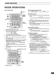
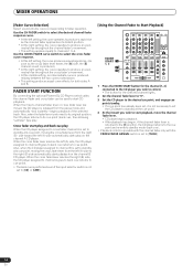
... HEADPHONES CUE (MASTER) button is selected, the master audio is output from the R channel. • When set to the [STEREO] position, the sound corresponding to the selected HEADPHONES CUE button is output in stereo. 3 When [MONO SPLIT] is selected, use the MIXING dial to adjust the balance of L+R channels. [Microphone Input] 1 To use the MIC 2 LEVEL dial to adjust the sound volume of MIC 2. 3 Use the microphone equalizer dials (HI, LOW) to adjust the tone of the microphone sound. • The microphone equalizer function operates simultaneously on microphone 1 and 2. [Booth Monitor Output...
... HEADPHONES CUE (MASTER) button is selected, the master audio is output from the R channel. • When set to the [STEREO] position, the sound corresponding to the selected HEADPHONES CUE button is output in stereo. 3 When [MONO SPLIT] is selected, use the MIXING dial to adjust the balance of L+R channels. [Microphone Input] 1 To use the MIC 2 LEVEL dial to adjust the sound volume of MIC 2. 3 Use the microphone equalizer dials (HI, LOW) to adjust the tone of the microphone sound. • The microphone equalizer function operates simultaneously on microphone 1 and 2. [Booth Monitor Output...
Owner's Manual
Page 14
... mixer's channel fader lever or cross fader lever are moved, the CD player is not set to standby at a cue point, moving the cross fader lever from the pause mode and automatically -and instantly - Cross fader start play and back cue play When the CD player assigned to cross fader channel A is set to [CD] or [LINE]. [Using the Channel Fader to Start Playback] FADER START 1 1, 2 2 4 1 Press the FADER START button for the channel (1, 2) connected to the CD player you wish to control...
... mixer's channel fader lever or cross fader lever are moved, the CD player is not set to standby at a cue point, moving the cross fader lever from the pause mode and automatically -and instantly - Cross fader start play and back cue play When the CD player assigned to cross fader channel A is set to [CD] or [LINE]. [Using the Channel Fader to Start Playback] FADER START 1 1, 2 2 4 1 Press the FADER START button for the channel (1, 2) connected to the CD player you wish to control...
Owner's Manual
Page 15
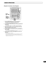
MIXER OPERATIONS [Using the Cross Fader to Start Playback] FADER START 1 1, 2 CROSS FADER 2 ASSIGN A / THRU / B 35 1 Press the FADER START button for the channel (1, 2) connected to the CD player you wish to control. • The button for the selected channel lights. 2 Set the CROSS FADER ASSIGN switch for the selected channel to [A] or [B]. • Select [A] to assign to cross fader channel A (left side). • Select [B] to assign to cross fader channel B (right side). 3 Move the cross fader lever to the full opposite...
MIXER OPERATIONS [Using the Cross Fader to Start Playback] FADER START 1 1, 2 CROSS FADER 2 ASSIGN A / THRU / B 35 1 Press the FADER START button for the channel (1, 2) connected to the CD player you wish to control. • The button for the selected channel lights. 2 Set the CROSS FADER ASSIGN switch for the selected channel to [A] or [B]. • Select [A] to assign to cross fader channel A (left side). • Select [B] to assign to cross fader channel B (right side). 3 Move the cross fader lever to the full opposite...
Owner's Manual
Page 16
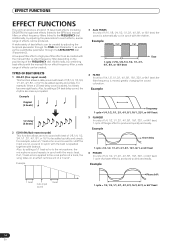
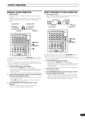
... parameter through beat effects linked to the BPM and manual filters or effect frequency filters linked to the vocal portion of a track, the song takes on the positioning of the FREQUENCY dial. Additionally, by adding a 3/4 beat delay sound, the rhythm becomes syncopated. A low-pass filter effect or high-pass filter effect can be created with the music beat. If a 1/1 beat echo is moved, greatly changing the sound coloration. EFFECT FUNCTIONS EFFECT FUNCTIONS This unit...
... parameter through beat effects linked to the BPM and manual filters or effect frequency filters linked to the vocal portion of a track, the song takes on the positioning of the FREQUENCY dial. Additionally, by adding a 3/4 beat delay sound, the rhythm becomes syncopated. A low-pass filter effect or high-pass filter effect can be created with the music beat. If a 1/1 beat echo is moved, greatly changing the sound coloration. EFFECT FUNCTIONS EFFECT FUNCTIONS This unit...
Owner's Manual
Page 18
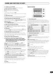
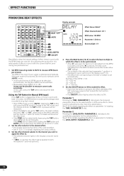
... selected channel lights in the display's channel name area. • If [MIC] is selected, the effect will be applied to both microphone 1 and microphone 2. 4 Press the BEAT button ( , ) to select the beat multiple to which the TAP button is displayed in synch with the BPM (beats per minute). EFFECT FUNCTIONS PRODUCING BEAT EFFECTS Display example 4 BEAT 2, 3 TAP 1 AUTO 1234 AUTO TAP ABM MIDI BPM % mS Effect Name: DELAY Effect Channel Select: CH 1 BPM value: 120 BPM Parameter 1: 500 ms 2 3 TIME LEVEL...
... selected channel lights in the display's channel name area. • If [MIC] is selected, the effect will be applied to both microphone 1 and microphone 2. 4 Press the BEAT button ( , ) to select the beat multiple to which the TAP button is displayed in synch with the BPM (beats per minute). EFFECT FUNCTIONS PRODUCING BEAT EFFECTS Display example 4 BEAT 2, 3 TAP 1 AUTO 1234 AUTO TAP ABM MIDI BPM % mS Effect Name: DELAY Effect Channel Select: CH 1 BPM value: 120 BPM Parameter 1: 500 ms 2 3 TIME LEVEL...
Owner's Manual
Page 19
... the display's channel name section. • When [MIC] is selected, the effect will appear in strong changes to the FREQUENCY dial. Through FREQUENCY Through LPF HPF Frequency Beat effect Frequency Beat effect 1 FILTER 3 FREQUENCY 2 2 FILTER 3 FREQUENCY The manual effecter is linked to the left produces low-pass filter effects. The beat effect is applied only to the selected frequency band. • The function is not supported when SEND/RETURN...
... the display's channel name section. • When [MIC] is selected, the effect will appear in strong changes to the FREQUENCY dial. Through FREQUENCY Through LPF HPF Frequency Beat effect Frequency Beat effect 1 FILTER 3 FREQUENCY 2 2 FILTER 3 FREQUENCY The manual effecter is linked to the left produces low-pass filter effects. The beat effect is applied only to the selected frequency band. • The function is not supported when SEND/RETURN...
Owner's Manual
Page 21
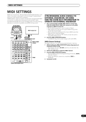
...channel is completed, [END] is displayed. 4 Set power to OFF. The DJM-700-S/DJM-700-K uses the MIDI protocol for transmitting data about component operation and BPM (timing clock). DJ CD Player OUT Audio IN BPM =120 MIDI sequencer BPM =120 IN MIDI OUT MIDI START /STOP TIME SYNCHRONIZING AUDIO SIGNALS TO EXTERNAL SEQUENCER, OR USING DJM-700-S/DJM-700-K INFORMATION TO OPERATE AN EXTERNAL SEQUENCER 1 Use a commercially available MIDI cable to connect the DJM-700-S/DJM-700-K's MIDI OUT connector to the MIDI sequencer's MIDI IN connector. • Set the MIDI sequencer's synch mode...
...channel is completed, [END] is displayed. 4 Set power to OFF. The DJM-700-S/DJM-700-K uses the MIDI protocol for transmitting data about component operation and BPM (timing clock). DJ CD Player OUT Audio IN BPM =120 MIDI sequencer BPM =120 IN MIDI OUT MIDI START /STOP TIME SYNCHRONIZING AUDIO SIGNALS TO EXTERNAL SEQUENCER, OR USING DJM-700-S/DJM-700-K INFORMATION TO OPERATE AN EXTERNAL SEQUENCER 1 Use a commercially available MIDI cable to connect the DJM-700-S/DJM-700-K's MIDI OUT connector to the MIDI sequencer's MIDI IN connector. • Set the MIDI sequencer's synch mode...
Owner's Manual
Page 24
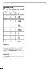
EFFSEL1 0 1 0 1 0 1 1 0 1 1 0 0 1 1 - DELAY ECHO TRANS FILTER FLANGER PHASER REVERB ROBOT CRUSH ROLL REV ROLL UP ROLL DWNROLL SND/RTN 1 2 3 4 MIC CF.A CF.B MASTER SNAPSHOT Once the DJM-700-S/DJM-700-K is setup with parameters for control change and program change are supported. 24 En Hold the MIDI START/STOP button depressed to control whether the MIDI control signal is selected, however, timing clock and snap shot functions are transmitted. When snapshot of parameters can be recorded as a snapshot. MIDI ON...
EFFSEL1 0 1 0 1 0 1 1 0 1 1 0 0 1 1 - DELAY ECHO TRANS FILTER FLANGER PHASER REVERB ROBOT CRUSH ROLL REV ROLL UP ROLL DWNROLL SND/RTN 1 2 3 4 MIC CF.A CF.B MASTER SNAPSHOT Once the DJM-700-S/DJM-700-K is setup with parameters for control change and program change are supported. 24 En Hold the MIDI START/STOP button depressed to control whether the MIDI control signal is selected, however, timing clock and snap shot functions are transmitted. When snapshot of parameters can be recorded as a snapshot. MIDI ON...
Owner's Manual
Page 25
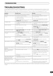
... not support MIDI timing clock cannot be correctly measurable with CD player. • The FADER START button is incorrect. • Correctly set to -6 dB, etc. • Set input selector to apply the effects. If the trouble cannot be measured. No sound, or sound volume is too low. • Input selector is set incorrectly. • Connection cables are connected incorrectly, or connections are loose. • Jacks or plugs are often mistaken for the desired channel. Measured BPM value...
... not support MIDI timing clock cannot be correctly measurable with CD player. • The FADER START button is incorrect. • Correctly set to -6 dB, etc. • Set input selector to apply the effects. If the trouble cannot be measured. No sound, or sound volume is too low. • Input selector is set incorrectly. • Connection cables are connected incorrectly, or connections are loose. • Jacks or plugs are often mistaken for the desired channel. Measured BPM value...

Owner's Manual
Page 26
... to purchase replacement parts, operating instructions, service manuals, or accessories, please call the number shown below. 800 - 782 - 7210 Please do not ship your product to Pioneer without first calling the Customer Support Division at rated output) LINE 104 dB PHONO 94 dB MIC 82 dB Distortion (LINE-MASTER 1 0.005 % Standard input level/Input impedance PHONO 2 to 4 52 dBu/47 kΩ MIC 1 52 dBu/22 kΩ LINE, LINE/CD 1 to...
... to purchase replacement parts, operating instructions, service manuals, or accessories, please call the number shown below. 800 - 782 - 7210 Please do not ship your product to Pioneer without first calling the Customer Support Division at rated output) LINE 104 dB PHONO 94 dB MIC 82 dB Distortion (LINE-MASTER 1 0.005 % Standard input level/Input impedance PHONO 2 to 4 52 dBu/47 kΩ MIC 1 52 dBu/22 kΩ LINE, LINE/CD 1 to...


