Owner's Manual
Page 2
... model properly. Do not use furniture wax or cleaners. ÷ Never use , the plug must not be fitted, please observe the wiring code as this unit, make sure the unit has been installed so that the power cord can be connected to the terminal which is obtained. However the method of after removal. NO USER-SERVICEABLE PARTS INSIDE. If the plug contains a removable fuse...
... model properly. Do not use furniture wax or cleaners. ÷ Never use , the plug must not be fitted, please observe the wiring code as this unit, make sure the unit has been installed so that the power cord can be connected to the terminal which is obtained. However the method of after removal. NO USER-SERVICEABLE PARTS INSIDE. If the plug contains a removable fuse...
Owner's Manual
Page 3
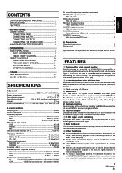
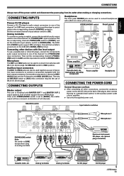
... 2. Accessories Operating Instructions 1 Power cord 1 Specifications and appearance are provided for each of CD and LINE/PHONO (MM type) inputs and two microphone inputs for synchronizing beat effects. 3) IN-LOOP sampler Detects the current track's BPM and records up to 5 of 4-beat sources in banks, and plays a loop in time with the track's BPM. 4 2 MIC input, AUX switching Equipped with 2 MIC input jacks that can be used to assign channel inputs and master outputs to the left and right channels of monitor headphones...
... 2. Accessories Operating Instructions 1 Power cord 1 Specifications and appearance are provided for each of CD and LINE/PHONO (MM type) inputs and two microphone inputs for synchronizing beat effects. 3) IN-LOOP sampler Detects the current track's BPM and records up to 5 of 4-beat sources in banks, and plays a loop in time with the track's BPM. 4 2 MIC input, AUX switching Equipped with 2 MIC input jacks that can be used to assign channel inputs and master outputs to the left and right channels of monitor headphones...
Owner's Manual
Page 4
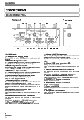
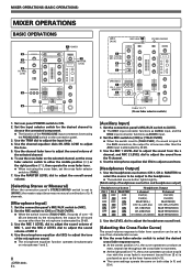
.... Use for microphone input, or for MM cartridge) or line level input connectors. When this connection is set to the [MONO] position, master output is made , the DJ mixer's fader lever can be used to connect a DJ CD player or other component with line level output. 13. Channel 2 CONTROL connector Ø3.5 mm mini-phone type connector. CONNECTIONS CONNECTIONS CONNECTION PANEL Rear panel 12 3 4 5 Front panel 6 18 POWER OFF ON AC IN MONO 1 MASTER OUT L R STEREO 2 MIC2 AUX(R) MIC MIC1 AUX(L) AUX PHONO LINE CD PHONO LINE L LINE PHONO R L LINE PHONO R CONTROL CD SIGNAL...
.... Use for microphone input, or for MM cartridge) or line level input connectors. When this connection is set to the [MONO] position, master output is made , the DJ mixer's fader lever can be used to connect a DJ CD player or other component with line level output. 13. Channel 2 CONTROL connector Ø3.5 mm mini-phone type connector. CONNECTIONS CONNECTIONS CONNECTION PANEL Rear panel 12 3 4 5 Front panel 6 18 POWER OFF ON AC IN MONO 1 MASTER OUT L R STEREO 2 MIC2 AUX(R) MIC MIC1 AUX(L) AUX PHONO LINE CD PHONO LINE L LINE PHONO R L LINE PHONO R CONTROL CD SIGNAL...
Owner's Manual
Page 5
...instrument, CD player, etc. (phone plug connection) Cassette deck, etc. MIC/AUX switch Input selector switches POWER OFF ON AC IN MONO 1 MASTER OUT L R STEREO 2 MIC2 AUX(R) MIC MIC1 AUX(L) AUX PHONO LINE CD PHONO LINE L LINE PHONO R L LINE PHONO R CONTROL CD SIGNAL GND CONTROL PHONO/LINE switch Note: Set switch to the MIC2 (AUX(R)) jack. Analog turntable Analog turntable DJ CD player DJ CD player 5 En CONNECTING INPUTS Pioneer DJ CD players Connect a DJ CD player's audio output connectors to one of the channel 1 to [AUX] (this connection requires the use a cassette deck...
...instrument, CD player, etc. (phone plug connection) Cassette deck, etc. MIC/AUX switch Input selector switches POWER OFF ON AC IN MONO 1 MASTER OUT L R STEREO 2 MIC2 AUX(R) MIC MIC1 AUX(L) AUX PHONO LINE CD PHONO LINE L LINE PHONO R L LINE PHONO R CONTROL CD SIGNAL GND CONTROL PHONO/LINE switch Note: Set switch to the MIC2 (AUX(R)) jack. Analog turntable Analog turntable DJ CD player DJ CD player 5 En CONNECTING INPUTS Pioneer DJ CD players Connect a DJ CD player's audio output connectors to one of the channel 1 to [AUX] (this connection requires the use a cassette deck...
Owner's Manual
Page 6
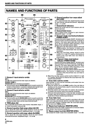
...OF PARTS NAMES AND FUNCTIONS OF PARTS 1 2 POWER 6 Channel equalizer low-range adjust MIC MIC 1 LEVEL CD 1 PHONO 1 /LINE 1 TRIM CD 2 PHONO 2 /LINE 2 TRIM MASTER LEVEL 13 dial (LOW) Use to adjust the bass (low-range) frequency sound for each channel (includes kill function). (Adjustable 24 3 2 CHANNEL DJ MIXER 3 14 range: -∞ to +9 dB) 0 0 7 Channel level indicators MIC 2 LEVEL + 9 BEAT EFFECTS + 9 Display the current level for each channel, with the cross fader selector switch. The button lights when set to ON. The button lights when set to cross fader...
...OF PARTS NAMES AND FUNCTIONS OF PARTS 1 2 POWER 6 Channel equalizer low-range adjust MIC MIC 1 LEVEL CD 1 PHONO 1 /LINE 1 TRIM CD 2 PHONO 2 /LINE 2 TRIM MASTER LEVEL 13 dial (LOW) Use to adjust the bass (low-range) frequency sound for each channel (includes kill function). (Adjustable 24 3 2 CHANNEL DJ MIXER 3 14 range: -∞ to +9 dB) 0 0 7 Channel level indicators MIC 2 LEVEL + 9 BEAT EFFECTS + 9 Display the current level for each channel, with the cross fader selector switch. The button lights when set to ON. The button lights when set to cross fader...
Owner's Manual
Page 7
... panel's MIC/AUX switch is set to [AUX], this dial adjusts the sound volume for synchronizing effects (P.11) The selected button lights. This is the default mode whenever power is set to [AUX], this dial adjusts the sound volume for the left channel (AUX(L)). 25 Microphone 2 level control dial (MIC 2 LEVEL) Use to adjust the volume of microphone 2. (Adjustable range -∞ to 0 dB) When the connection panel's MIC/AUX switch is first turned on the unit's front panel. 7 En If the TAP button is tapped in the AUTO mode, the mode automatically switches to the TAP mode (manual input...
... panel's MIC/AUX switch is set to [AUX], this dial adjusts the sound volume for synchronizing effects (P.11) The selected button lights. This is the default mode whenever power is set to [AUX], this dial adjusts the sound volume for the left channel (AUX(L)). 25 Microphone 2 level control dial (MIC 2 LEVEL) Use to adjust the volume of microphone 2. (Adjustable range -∞ to 0 dB) When the connection panel's MIC/AUX switch is first turned on the unit's front panel. 7 En If the TAP button is tapped in the AUTO mode, the mode automatically switches to the TAP mode (manual input...
Owner's Manual
Page 8
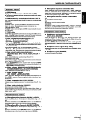
... the connection panel. 3. MIXER OPERATIONS (BASIC OPERATIONS) MIXER OPERATIONS BASIC OPERATIONS 2 MIC 3 TRIM 4 HI, MID, LOW 1 POWER MASTER BEAT EFFECTS 7 MASTER LEVEL HEADPHONES 5 [MIC] [AUX] MIC/AUX 1 MIC 3 MIC 1 LEVEL, MIC 2 LEVEL 4 EQ 2 STEREO/MONO MASTER BEAT EFFECTS [PHONES] 1 CH-1, CH-2, MASTER 2 LEVEL HEADPHONES 6 THRU/ / (Cross fader selector switch) 1. Set the input selector switch for all sound sources other than the microphone is set the cross fader selector switch to [MONO], the master output becomes a monaural combination of the selected channel...
... the connection panel. 3. MIXER OPERATIONS (BASIC OPERATIONS) MIXER OPERATIONS BASIC OPERATIONS 2 MIC 3 TRIM 4 HI, MID, LOW 1 POWER MASTER BEAT EFFECTS 7 MASTER LEVEL HEADPHONES 5 [MIC] [AUX] MIC/AUX 1 MIC 3 MIC 1 LEVEL, MIC 2 LEVEL 4 EQ 2 STEREO/MONO MASTER BEAT EFFECTS [PHONES] 1 CH-1, CH-2, MASTER 2 LEVEL HEADPHONES 6 THRU/ / (Cross fader selector switch) 1. Set the input selector switch for all sound sources other than the microphone is set the cross fader selector switch to [MONO], the master output becomes a monaural combination of the selected channel...
Owner's Manual
Page 9
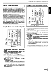
... instant you wish to start , the CD player assigned to the opposite side channel will return to the cue point and enter standby mode (back cue). * If the cross fader selector switch is set to standby at the cue point. 5. MIXER OPERATIONS (FADER START FUNCTION) English FADER START FUNCTION By connecting the optional Pioneer DJ CD Player control cable, the channel fader and cross fader can be used to start playback, move the cross fader lever. ¶ CD player begins playback. ¶ After...
... instant you wish to start , the CD player assigned to the opposite side channel will return to the cue point and enter standby mode (back cue). * If the cross fader selector switch is set to standby at the cue point. 5. MIXER OPERATIONS (FADER START FUNCTION) English FADER START FUNCTION By connecting the optional Pioneer DJ CD Player control cable, the channel fader and cross fader can be used to start playback, move the cross fader lever. ¶ CD player begins playback. ¶ After...
Owner's Manual
Page 10
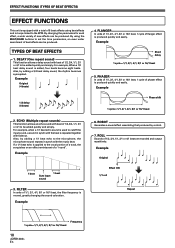
... effects using the BEAT/BANK buttons to be produced. By using beat effects and in-loops linked to cutoff the input sound, a sound in synch with beat of 1/2, 3/4, 1/1, 2/1 or 4/1 to set the time parameters, an even wider assortment of 1/1, 2/1, 4/1, 8/1 or 16/1 beat, the filter frequency is moved, greatly changing the sound coloration. ECHO (Multiple repeat sounds) This function allows an echo sound with the music beat. TYPES OF BEAT EFFECTS 1. Example Phase...
... effects using the BEAT/BANK buttons to be produced. By using beat effects and in-loops linked to cutoff the input sound, a sound in synch with beat of 1/2, 3/4, 1/1, 2/1 or 4/1 to set the time parameters, an even wider assortment of 1/1, 2/1, 4/1, 8/1 or 16/1 beat, the filter frequency is moved, greatly changing the sound coloration. ECHO (Multiple repeat sounds) This function allows an echo sound with the music beat. TYPES OF BEAT EFFECTS 1. Example Phase...
Owner's Manual
Page 11
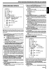
... =1 / 2 / MIC / MASTER 7 LEVEL/DEPTH 4 ON/OFF This function detects the current track's BPM, and 4 beat sources are recorded in 1-step increments. 2. Measure the BPM. ¶ Perform step 1 of the input sound is first turned ON, the function defaults to 999 in up to five memory banks, and played as the effect time. [Using the BEAT/PITCH buttons for 1 beat (1/4 notes) or 4 beats will cause the BPM mode to change to the TAP mode, and...
... =1 / 2 / MIC / MASTER 7 LEVEL/DEPTH 4 ON/OFF This function detects the current track's BPM, and 4 beat sources are recorded in 1-step increments. 2. Measure the BPM. ¶ Perform step 1 of the input sound is first turned ON, the function defaults to 999 in up to five memory banks, and played as the effect time. [Using the BEAT/PITCH buttons for 1 beat (1/4 notes) or 4 beats will cause the BPM mode to change to the TAP mode, and...
Owner's Manual
Page 12
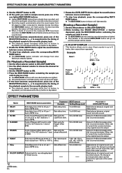
... 7 Set robot sound fixed values from -100 % to the currently playing track. ¶ The playback speed increases while the [+] button is depressed, and decreases while the [-] button is output. 6 ROBOT Robot sound effects can be erased. 8. of original sound and recorded sample. When dial is turned fully counterclockwise, only original sound is depressed. 6 Rotate the LEVEL/DEPTH dial to adjust the sound balance between original sound and echo sound. 3 FILTER...
... 7 Set robot sound fixed values from -100 % to the currently playing track. ¶ The playback speed increases while the [+] button is depressed, and decreases while the [-] button is output. 6 ROBOT Robot sound effects can be erased. 8. of original sound and recorded sample. When dial is turned fully counterclockwise, only original sound is depressed. 6 Rotate the LEVEL/DEPTH dial to adjust the sound balance between original sound and echo sound. 3 FILTER...
Owner's Manual
Page 13
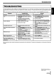
... TAP button to the CD player. ÷ Effect channel selector (CH. Symptom No power No sound, or sound volume is incorrect. Measured BPM value is too low. The measured BPM value is necessary. Sometimes the trouble may cause the unit to differences in use. Thus, also check the other than [THRU]. ÷ Set the FADER START button to ON. ÷ Use a control cable to connect the CONTROL jacks of DJM-400 and CD player. ÷ Connect both the CONTROL jacks...
... TAP button to the CD player. ÷ Effect channel selector (CH. Symptom No power No sound, or sound volume is incorrect. Measured BPM value is too low. The measured BPM value is necessary. Sometimes the trouble may cause the unit to differences in use. Thus, also check the other than [THRU]. ÷ Set the FADER START button to ON. ÷ Use a control cable to connect the CONTROL jacks of DJM-400 and CD player. ÷ Connect both the CONTROL jacks...
Owner's Manual
Page 76
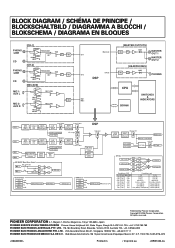
... Level Meter CF assign THRU CH1 CUE CH2 Fader CUE Monitor [CH2] BEAT EFFECTS [CH2](post) Cross Fader CH2 Level Meter CH2 CUE MIC ON/OFF Mono/Stereo Convert BPM detect [MIC] 2-Band MIC EQ MIC ON/OFF Mono/Stereo Convert MIC OFF/ON MIC 1 L R MIC 2 L MIC/AUX R BEAT EFFECTS CH1 CH2 MIC Master Effect Processor L MIC out R Mix Ratio Effect out BPM detect CH1 CH2 MIC Master DSP Talk Over Talk Over Detection Filter BEAT EFFECTS [MIC] BPM Counter CH-1 CH-2 MASTER Send to CPU BPM detect [Master] BEAT EFFECTS [Master] Master VR Master Level Meter Master out CH1 CUE CH2 CUE...
... Level Meter CF assign THRU CH1 CUE CH2 Fader CUE Monitor [CH2] BEAT EFFECTS [CH2](post) Cross Fader CH2 Level Meter CH2 CUE MIC ON/OFF Mono/Stereo Convert BPM detect [MIC] 2-Band MIC EQ MIC ON/OFF Mono/Stereo Convert MIC OFF/ON MIC 1 L R MIC 2 L MIC/AUX R BEAT EFFECTS CH1 CH2 MIC Master Effect Processor L MIC out R Mix Ratio Effect out BPM detect CH1 CH2 MIC Master DSP Talk Over Talk Over Detection Filter BEAT EFFECTS [MIC] BPM Counter CH-1 CH-2 MASTER Send to CPU BPM detect [Master] BEAT EFFECTS [Master] Master VR Master Level Meter Master out CH1 CUE CH2 CUE...


