Service Manual
Page 1
...-CD/DAB CONTROL DSP HIGH POWER CD PLAYER WITH RDS TUNER DEH-P900R UC MULTI-CD CONTROL DSP HIGH POWER CD PLAYER WITH FM/AM TUNER DEH-P9050 ES - When replacing IC601 PD5484A, use PD5483B as IC601, and then remove the 3 parts listed above . PIONEER ELECTRONIC [EUROPE] N.V. CONTENTS 1. SAFETY INFORMATION 2 2. PCB CONNECTION DIAGRAM 32 5. When replacing IC601 PD5483A, use PD5484B as IC601, and then remove the 3 parts listed above . OPERATIONS AND SPECIFICATIONS 83 PIONEER ELECTRONIC...
...-CD/DAB CONTROL DSP HIGH POWER CD PLAYER WITH RDS TUNER DEH-P900R UC MULTI-CD CONTROL DSP HIGH POWER CD PLAYER WITH FM/AM TUNER DEH-P9050 ES - When replacing IC601 PD5484A, use PD5483B as IC601, and then remove the 3 parts listed above . PIONEER ELECTRONIC [EUROPE] N.V. CONTENTS 1. SAFETY INFORMATION 2 2. PCB CONNECTION DIAGRAM 32 5. When replacing IC601 PD5483A, use PD5484B as IC601, and then remove the 3 parts listed above . OPERATIONS AND SPECIFICATIONS 83 PIONEER ELECTRONIC...
Service Manual
Page 2
... product contains lead in solder and certain electrical parts contain chemicals which are not qualified to properly and safely repair complex products such as those covered by a short pin). 2. During disassembly, be sure to turn the power off since an internal IC might be taken to cause cancer, birth defects or other reproductive harm. DEH-P900R,P9050 -
... product contains lead in solder and certain electrical parts contain chemicals which are not qualified to properly and safely repair complex products such as those covered by a short pin). 2. During disassembly, be sure to turn the power off since an internal IC might be taken to cause cancer, birth defects or other reproductive harm. DEH-P900R,P9050 -
Service Manual
Page 4
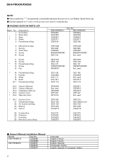
... unavailable because they are used * 20-7 Caution Card 21 Polyethylene Bag 22 Air Cushioned Bag 23 Battery 24 Carton CRP1209 CEG1185 CEG1192 CEX1006 CHG3772 CRP1210 CEG1088(Cover) CEG1192 CEX1006 CHG3770 25 Contain Box 26 Protector 27 Protector 28 Remote Control Assy CHL3772 CHP2032 CHP2033 CXB3875 CHL3770 CHP2032 CHP2033 CXB3875 - Owner's Manual, Installation Manual Model Part No. DEH-P9050/ES CDE5854 CEA2426...
... unavailable because they are used * 20-7 Caution Card 21 Polyethylene Bag 22 Air Cushioned Bag 23 Battery 24 Carton CRP1209 CEG1185 CEG1192 CEX1006 CHG3772 CRP1210 CEG1088(Cover) CEG1192 CEX1006 CHG3770 25 Contain Box 26 Protector 27 Protector 28 Remote Control Assy CHL3772 CHP2032 CHP2033 CXB3875 CHL3770 CHP2032 CHP2033 CXB3875 - Owner's Manual, Installation Manual Model Part No. DEH-P9050/ES CDE5854 CEA2426...
Service Manual
Page 10
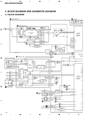
1 2 3 4 DEH-P900R,P9050 3. BLOCK DIAGRAM AND SCHEMATIC DIAGRAM 3.1 BLOCK DIAGRAM A A TUNER AMP UNIT E ASL UNIT MIC4501 Q4501 VR4501 ASL A 3 IC 45 NJM2 ANT GND2 B CN451 1 2 B FM/AM TUNER UNIT FM FRONT END Q3 FM/AM 1ST IF 10.7MHz ...POWER ON MUTE IC 401 S-81250SGUP B.U CN101 IP-BUS CONNECTOR RDS DECODER 24 20 IC 501 PM4009A 11 12 X501 Q501 VDD fm/AM /UC Q101 B.U ASENBO 8 5 BUS2 1 BUS1 Q102 IP-BUS DRIVER 5 IC 101 1 TX 6 CA008AM 2 RX 8 IPPW 7 BUS+L 11 BUS-L PICKUP UNIT(SERVICE) LD MD LD+ MD HOLOGRAM UNIT FOCUS ACT FO+ TRACKING ACT TO+ H CONTROL UNIT...
1 2 3 4 DEH-P900R,P9050 3. BLOCK DIAGRAM AND SCHEMATIC DIAGRAM 3.1 BLOCK DIAGRAM A A TUNER AMP UNIT E ASL UNIT MIC4501 Q4501 VR4501 ASL A 3 IC 45 NJM2 ANT GND2 B CN451 1 2 B FM/AM TUNER UNIT FM FRONT END Q3 FM/AM 1ST IF 10.7MHz ...POWER ON MUTE IC 401 S-81250SGUP B.U CN101 IP-BUS CONNECTOR RDS DECODER 24 20 IC 501 PM4009A 11 12 X501 Q501 VDD fm/AM /UC Q101 B.U ASENBO 8 5 BUS2 1 BUS1 Q102 IP-BUS DRIVER 5 IC 101 1 TX 6 CA008AM 2 RX 8 IPPW 7 BUS+L 11 BUS-L PICKUP UNIT(SERVICE) LD MD LD+ MD HOLOGRAM UNIT FOCUS ACT FO+ TRACKING ACT TO+ H CONTROL UNIT...
Service Manual
Page 11
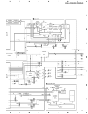
...SUB WOOFER L CH ILL asens bsens TELIN B.U DRSYS DRSENS Q932 Q931 Q951 Q681 Q682 Q683 B.U DRELAY Q941 Q942 B.U B.U B.U BACKUP 1 2 RL- 9 RL+ 11 FL- 10 FL+ 12 B.REM 4 ILL 3 ACC 5 TEL1 8 DOOR SW 7 ALARM 6 SYS+B Q921 Q923 B.U Q981 Q922 RESET 1 IC 961 2 S-80735ANDZI VDD Q803 B.U Q808 Q801 B.U Q802 C KEYBOARD UNIT CN801 12 9 8 VDD 6 2 11 4 5 REMOTE CONTROL...GND RL- FL+ B.REM ILL ACC MUTE DOOR SW C ALARM D 11 5 6 7 8 DEH-P900R,P9050 501 ASL AMP 3 IC 4501 1 NJM2068 ASL FILTER 3 IC 4502 NJM2068 12 CN141 2 NOISE D DSP UNIT DOUT SCKO LRCK CN252 4 3 2 ...
...SUB WOOFER L CH ILL asens bsens TELIN B.U DRSYS DRSENS Q932 Q931 Q951 Q681 Q682 Q683 B.U DRELAY Q941 Q942 B.U B.U B.U BACKUP 1 2 RL- 9 RL+ 11 FL- 10 FL+ 12 B.REM 4 ILL 3 ACC 5 TEL1 8 DOOR SW 7 ALARM 6 SYS+B Q921 Q923 B.U Q981 Q922 RESET 1 IC 961 2 S-80735ANDZI VDD Q803 B.U Q808 Q801 B.U Q802 C KEYBOARD UNIT CN801 12 9 8 VDD 6 2 11 4 5 REMOTE CONTROL...GND RL- FL+ B.REM ILL ACC MUTE DOOR SW C ALARM D 11 5 6 7 8 DEH-P900R,P9050 501 ASL AMP 3 IC 4501 1 NJM2068 ASL FILTER 3 IC 4502 NJM2068 12 CN141 2 NOISE D DSP UNIT DOUT SCKO LRCK CN252 4 3 2 ...
Service Manual
Page 12
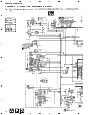
... /UC IP-BUS:+2.2dBs FM(100%):-20.5dBs AM(30%):-31dBs B FM/AM TUNER UNIT C433 100P TUNER C /ES EEPROM D 12 A F G 1 2 RDS DECODER /UC 3 AUTOMATIC FLAP S951 CSN1012 S952 CLOSE CSN1022 OPEN M951 AUTOMATIC FLAP MOTOR CXM1085 F SWITCH PCB 4 CK 1 2 3 4 DEH-P900R,P9050 3.2 OVERALL CONNECTION DIAGRAM(GUIDE PAGE) Note: When ordering service parts, be sure to refer to "EXPLODED VIEWS AND PARTS LIST" or...
... /UC IP-BUS:+2.2dBs FM(100%):-20.5dBs AM(30%):-31dBs B FM/AM TUNER UNIT C433 100P TUNER C /ES EEPROM D 12 A F G 1 2 RDS DECODER /UC 3 AUTOMATIC FLAP S951 CSN1012 S952 CLOSE CSN1022 OPEN M951 AUTOMATIC FLAP MOTOR CXM1085 F SWITCH PCB 4 CK 1 2 3 4 DEH-P900R,P9050 3.2 OVERALL CONNECTION DIAGRAM(GUIDE PAGE) Note: When ordering service parts, be sure to refer to "EXPLODED VIEWS AND PARTS LIST" or...
Service Manual
Page 32
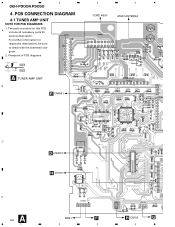
PCB CONNECTION DIAGRAM 4.1 TUNER AMP UNIT NOTE FOR PCB DIAGRAMS 1. For further information for several destination. Viewpoint of PCB diagrams Connector Capacitor SIDE A P.C.Board Chip Part SIDE B A TUNER AMP UNIT B E CN4501 3 4 CORD ASSY MAIN ANTENNA PRE OUT C D CN3001 H CN701 D A 32 1 M951 F 2 3 H CN702 G 4 1 2 DEH-P900R,P9050 4. The parts mounted on this PCB A include all necessary parts for respective destinations, be sure to check with the schematic diagram. 2.
PCB CONNECTION DIAGRAM 4.1 TUNER AMP UNIT NOTE FOR PCB DIAGRAMS 1. For further information for several destination. Viewpoint of PCB diagrams Connector Capacitor SIDE A P.C.Board Chip Part SIDE B A TUNER AMP UNIT B E CN4501 3 4 CORD ASSY MAIN ANTENNA PRE OUT C D CN3001 H CN701 D A 32 1 M951 F 2 3 H CN702 G 4 1 2 DEH-P900R,P9050 4. The parts mounted on this PCB A include all necessary parts for respective destinations, be sure to check with the schematic diagram. 2.

Service Manual
Page 54
... not to connect the channel 1 negative probe of the unit is used for about one minute to allow the circuits to stabilize. • Since the protective systems in the PLAY mode. *The unit will be damaged due to adhesion of the lenses). • Jump operation of TRs other than 100TR continues after switching regulator ON, let the player run for adjusting the...
... not to connect the channel 1 negative probe of the unit is used for about one minute to allow the circuits to stabilize. • Since the protective systems in the PLAY mode. *The unit will be damaged due to adhesion of the lenses). • Jump operation of TRs other than 100TR continues after switching regulator ON, let the player run for adjusting the...
Service Manual
Page 58
... and DSEC. CRG can be moved from the users and also for facilitating trouble analysis and repair work . An intended operation continues in these errors). DEH-P900R,P9050 7. DTNO remains in servicing. (1) Basic Indication Method 1) When SERRORM is selected for the CSMOD (CD mode area for the system), error codes are not displayed (because a CD is turned off in this case. Upper digits of LCD...
... and DSEC. CRG can be moved from the users and also for facilitating trouble analysis and repair work . An intended operation continues in these errors). DEH-P900R,P9050 7. DTNO remains in servicing. (1) Basic Indication Method 1) When SERRORM is selected for the CSMOD (CD mode area for the system), error codes are not displayed (because a CD is turned off in this case. Upper digits of LCD...

Service Manual
Page 59
... failure on servo. 42 Electricity Sub-code unreadable. Note: Mechanical errors during aging are displayed. During setup, operational status of the [SOURCE] key, and inserting the disc. Last address memory function was unreadable for the source through the same operations as off focus, spindle unlocking, unreadable sub-code, or sound skipping occurs after setup, its cause and time occurred (in the servicing and efficiency of whether the S-CD...
... failure on servo. 42 Electricity Sub-code unreadable. Note: Mechanical errors during aging are displayed. During setup, operational status of the [SOURCE] key, and inserting the disc. Last address memory function was unreadable for the source through the same operations as off focus, spindle unlocking, unreadable sub-code, or sound skipping occurs after setup, its cause and time occurred (in the servicing and efficiency of whether the S-CD...

Service Manual
Page 63
Remove the screw A, four screws C, and then remove the Antenna Cable and Holder. 2. Remove the screw B. 3. Remove the three solder of tabs indicated by arrows, and then remove the Case. 2. Disconnect the connector, and then remove the DSP Unit. Stretch the four tabs, and then remove the Tuner Amp Unit. C Tuner Amp Unit Case DSP Unit 63 Remove the DSP Unit 1. Remove the Tuner Amp Unit (2/2) 1. DEH-P900R,P9050 Antenna Cable A Holder B CC C - -
Remove the screw A, four screws C, and then remove the Antenna Cable and Holder. 2. Remove the screw B. 3. Remove the three solder of tabs indicated by arrows, and then remove the Case. 2. Disconnect the connector, and then remove the DSP Unit. Stretch the four tabs, and then remove the Tuner Amp Unit. C Tuner Amp Unit Case DSP Unit 63 Remove the DSP Unit 1. Remove the Tuner Amp Unit (2/2) 1. DEH-P900R,P9050 Antenna Cable A Holder B CC C - -
Service Manual
Page 70
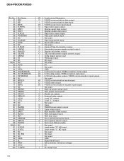
...NC LEVELR LEVELL NC SD_BW NC VSS5 SL VREF VCC4 TUNPDI I/O Function and Operation O P-BUS communication data output I P-BUS communication data input I/O P-BUS serial clock input/output O Flap motor open output O Display serial data output I Display enable data input O Flap motor close output I Flap open switch input Not used I Flap close switch input O Alarm LED output Not used O Inside of flap illumination output O Illumination power supply control output O Display chip select output O OEL module power supply control output I Grille detach sense input I FM stereo input...
...NC LEVELR LEVELL NC SD_BW NC VSS5 SL VREF VCC4 TUNPDI I/O Function and Operation O P-BUS communication data output I P-BUS communication data input I/O P-BUS serial clock input/output O Flap motor open output O Display serial data output I Display enable data input O Flap motor close output I Flap open switch input Not used I Flap close switch input O Alarm LED output Not used O Inside of flap illumination output O Illumination power supply control output O Display chip select output O OEL module power supply control output I Grille detach sense input I FM stereo input...

Service Manual
Page 72
... 50 51 26 I/O Format Function and Operation Not used I Remote control reception I External data BUS width select input I Processor mode select input Not used I Reset input O Crystal oscillating element connection pin GND I Crystal oscillating element connection pin VDD I NMI input Not used I Key data 1-4 I/O Key strobe input/output 1-6 Not used O C Dual illumination O C Key data output I Display data input Not used O C OEL controller ON I OEL controller ready input Not used I Hold input Not used O C Read strobe Not used O C Write strobe Not...
... 50 51 26 I/O Format Function and Operation Not used I Remote control reception I External data BUS width select input I Processor mode select input Not used I Reset input O Crystal oscillating element connection pin GND I Crystal oscillating element connection pin VDD I NMI input Not used I Key data 1-4 I/O Key strobe input/output 1-6 Not used O C Dual illumination O C Key data output I Display data input Not used O C OEL controller ON I OEL controller ready input Not used I Hold input Not used O C Read strobe Not used O C Write strobe Not...
Service Manual
Page 74
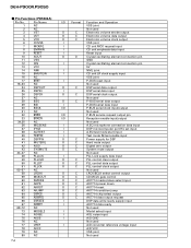
... output I P-BUS serial data input I/O P-BUS serial clock input/output Not used I/O P-BUS service request output pin I/O Reception enable input/output Not used I A.EQ microphone connection data input I DSP microcomputer port Hiz set input I A.EQ test mode start input I Test mode IN/test enable input O C Power supply for DSP O C Hard mute output O C Digital zero output O C System mute output Not used I PLL Lock supply data input O C PLL control clear output O C PLL control data output O C PLL control clock output Not used O C LRCK/BCLK select control...
... output I P-BUS serial data input I/O P-BUS serial clock input/output Not used I/O P-BUS service request output pin I/O Reception enable input/output Not used I A.EQ microphone connection data input I DSP microcomputer port Hiz set input I A.EQ test mode start input I Test mode IN/test enable input O C Power supply for DSP O C Hard mute output O C Digital zero output O C System mute output Not used I PLL Lock supply data input O C PLL control clear output O C PLL control data output O C PLL control clock output Not used O C LRCK/BCLK select control...

Service Manual
Page 79
...not use select for internal RF amplifier Analog circuit GND O Focus drive output O Tracking drive output O Sled drive output O Spindle drive output O DAC output for adjustment O DAC output for adjustment O DAC output for adjustment O DAC output for adjustment Power supply terminal to analog circuit O EFM signal output I EFM comparator reference voltage input 3T detection capacitor additional pin I RF signal input for EFM data regulation O RF signal output of after gain adjustment I RF-AGC amplifier input O RF summing amplifier output RF amplifier equalizer parts...
...not use select for internal RF amplifier Analog circuit GND O Focus drive output O Tracking drive output O Sled drive output O Spindle drive output O DAC output for adjustment O DAC output for adjustment O DAC output for adjustment O DAC output for adjustment Power supply terminal to analog circuit O EFM signal output I EFM comparator reference voltage input 3T detection capacitor additional pin I RF signal input for EFM data regulation O RF signal output of after gain adjustment I RF-AGC amplifier input O RF summing amplifier output RF amplifier equalizer parts...
Service Manual
Page 81
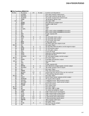
... P-Bus can be received 52 bsrq O C P-Bus polling request output 53, 54 NC Not used Open 55 CONT O C Servo driver power supply control output 56 CDMUTE O C CD mute control output 57 CDEJET O C Load/Eject motor Eject control output 58 CDLOAD O C Load/Eject motor Load control output 59 BMUTE O C Bus mute output 60 clamp I Disc clamp input 61, 62 NC Not used Open 63-66 NC Not used VDD or VSS 67 TXARI I Tx output set selection input 68 fsck O C Flash writing clock input...
... P-Bus can be received 52 bsrq O C P-Bus polling request output 53, 54 NC Not used Open 55 CONT O C Servo driver power supply control output 56 CDMUTE O C CD mute control output 57 CDEJET O C Load/Eject motor Eject control output 58 CDLOAD O C Load/Eject motor Load control output 59 BMUTE O C Bus mute output 60 clamp I Disc clamp input 61, 62 NC Not used Open 63-66 NC Not used VDD or VSS 67 TXARI I Tx output set selection input 68 fsck O C Flash writing clock input...
Service Manual
Page 83
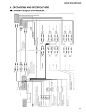
..., do not connect anything to the speaker leads that are not connected to speakers. Left Rear speaker Rear speaker Subwoofer Connecting cords with power regardless of any connections. OPERATIONS AND SPECIFICATIONS - Orange/White To lighting switch terminal. Fuse resistor Black (ground) To vehicle (metal) body. 83 ASL unit Antenna jack Front output Rear output Multi-CD player (sold separately) IP-BUS cable This Product IP-BUS input (Blue) Yellow/black If you use a cellular telephone, connect it via the Audio Mute lead on...
..., do not connect anything to the speaker leads that are not connected to speakers. Left Rear speaker Rear speaker Subwoofer Connecting cords with power regardless of any connections. OPERATIONS AND SPECIFICATIONS - Orange/White To lighting switch terminal. Fuse resistor Black (ground) To vehicle (metal) body. 83 ASL unit Antenna jack Front output Rear output Multi-CD player (sold separately) IP-BUS cable This Product IP-BUS input (Blue) Yellow/black If you use a cellular telephone, connect it via the Audio Mute lead on...
Service Manual
Page 84
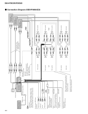
Connection Diagram (DEH-P9050/ES) 84 ASL unit Antenna jack Front output Rear output Multi-CD player (sold separately). With a 2 speaker system, do not connect anything to the speaker leads that are not connected to speakers. Fuse holder Red Fuse resistor To electric terminal controlled by ignition switch (12 V DC) ON/OFF. Left Rear speaker Rear speaker Subwoofer Connecting cords with power regardless of ignition switch position. DEH-P900R,P9050 - If not, keep the Audio Mute lead free of the power amp or Auto-antenna relay control terminal...
Connection Diagram (DEH-P9050/ES) 84 ASL unit Antenna jack Front output Rear output Multi-CD player (sold separately). With a 2 speaker system, do not connect anything to the speaker leads that are not connected to speakers. Fuse holder Red Fuse resistor To electric terminal controlled by ignition switch (12 V DC) ON/OFF. Left Rear speaker Rear speaker Subwoofer Connecting cords with power regardless of ignition switch position. DEH-P900R,P9050 - If not, keep the Audio Mute lead free of the power amp or Auto-antenna relay control terminal...
Service Manual
Page 86
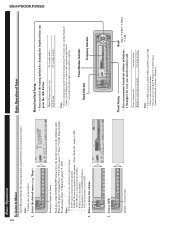
... Preset Tuning • You can memorize broadcast stations in the Multi-CD player. * AUX (external input) is set in buttons 1 through 6. Select the desired source (e.g. Source OFF. Each press of time you stop pressing the button. • "" stereo indicator lights when a stereo station is selected. Seek Tuning starts as soon as you press the 2/3 button. DEH-P900R,P9050 86 Basic Operation To Listen to Music The following cases, the sound source will not change: * No TV tuner...
... Preset Tuning • You can memorize broadcast stations in the Multi-CD player. * AUX (external input) is set in buttons 1 through 6. Select the desired source (e.g. Source OFF. Each press of time you stop pressing the button. • "" stereo indicator lights when a stereo station is selected. Seek Tuning starts as soon as you press the 2/3 button. DEH-P900R,P9050 86 Basic Operation To Listen to Music The following cases, the sound source will not change: * No TV tuner...
Service Manual
Page 88
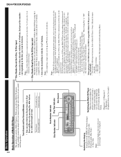
... Display Each press of the DISPLAY button changes the display in the following two functions. DEH-P900R,P9050 88 Basic Operation Basic Operation of Multi-CD Player This product can control a Multi-CD player. (With certain old type Multi-CD players, using a multiple connection adapter lets you connect multiple units which you can control with the 1 to 6 buttons. Magazine 1 = Magazine 2 = Magazine 3 (Displayed about for 2 seconds.) Disc Number Search (for 6-Disc, 12-Disc types) • You can select discs directly...
... Display Each press of the DISPLAY button changes the display in the following two functions. DEH-P900R,P9050 88 Basic Operation Basic Operation of Multi-CD Player This product can control a Multi-CD player. (With certain old type Multi-CD players, using a multiple connection adapter lets you connect multiple units which you can control with the 1 to 6 buttons. Magazine 1 = Magazine 2 = Magazine 3 (Displayed about for 2 seconds.) Disc Number Search (for 6-Disc, 12-Disc types) • You can select discs directly...


