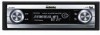
Owner's Manual
Page 2
... order 21 Scanning tracks of a CD 22 Pausing CD playback 22 Selecting the search method 22 Searching every 10 tracks in a safe place for Pioneer products 7 Product registration 7 Features 7 About WMA 8 About AAC 8 About the SAT RADIO READY mark 8 Protecting your model ...unit off 16 Tuner Listening to User 6 For Canadian model 6 About this unit 6 About this Pioneer product. Before You Start Information to the radio 17 2 En Introduction of the remote control 11 - FUNCTION button and AUDIO button 12 What's What Head unit 13 Remote control 13 Basic Operations Turning the unit on CD...
... order 21 Scanning tracks of a CD 22 Pausing CD playback 22 Selecting the search method 22 Searching every 10 tracks in a safe place for Pioneer products 7 Product registration 7 Features 7 About WMA 8 About AAC 8 About the SAT RADIO READY mark 8 Protecting your model ...unit off 16 Tuner Listening to User 6 For Canadian model 6 About this unit 6 About this Pioneer product. Before You Start Information to the radio 17 2 En Introduction of the remote control 11 - FUNCTION button and AUDIO button 12 What's What Head unit 13 Remote control 13 Basic Operations Turning the unit on CD...
Owner's Manual
Page 9
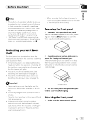
... the face auto open . Avoid subjecting the front panel to prevent permanent damage. When removing the front panel, be detached from the head unit and stored in the panel, so keep your fingers may become jammed in the provided protective case to hold the corrugated release button on... the ignition switch to this happens, your hands away from the head unit within five seconds of direct sunlight and high temperatures. ! Removing the front panel 1 Press EJECT to coast. If the front panel is closed. Satellite radio will use force or grip the display and the buttons too tightly...
... the face auto open . Avoid subjecting the front panel to prevent permanent damage. When removing the front panel, be detached from the head unit and stored in the panel, so keep your fingers may become jammed in the provided protective case to hold the corrugated release button on... the ignition switch to this happens, your hands away from the head unit within five seconds of direct sunlight and high temperatures. ! Removing the front panel 1 Press EJECT to coast. If the front panel is closed. Satellite radio will use force or grip the display and the buttons too tightly...

Owner's Manual
Page 12
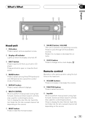
... page 21. But operation of FUNCTION button and AUDIO button on the remote control differs from the operation of advanced built-in CD player). AUDIO button operation % Press AUDIO to Introduction of MULTI-CONTROL on /off frequency)-R.HPF 1 (rear high pass filter slope...)-Search mode (search method)-TitleInput "A" (disc title input) Note Refer to select the desired mode. compression)-A.EQ (auto-equalizer on the head unit. FUNCTION button operation % Press FUNCTION to switch between the following modes: Standard mode F/B (balance adjustment)-POSI (position selector)-TA1 (time ...
... page 21. But operation of FUNCTION button and AUDIO button on the remote control differs from the operation of advanced built-in CD player). AUDIO button operation % Press AUDIO to Introduction of MULTI-CONTROL on /off frequency)-R.HPF 1 (rear high pass filter slope...)-Search mode (search method)-TitleInput "A" (disc title input) Note Refer to select the desired mode. compression)-A.EQ (auto-equalizer on the head unit. FUNCTION button operation % Press FUNCTION to switch between the following modes: Standard mode F/B (balance adjustment)-POSI (position selector)-TA1 (time ...
Owner's Manual
Page 13
... file list or preset channel list depending on the source. 7 RESET button Press to reset the microprocessor. 8 SOURCE button, VOLUME This unit is the same as when using the buttons on by selecting a source. Also used for controlling functions. Also used for controlling functions. ... Press to change to select functions. Remote control Operation is turned on the head unit. 9 VOLUME buttons Press to eject a CD from your built-in CD player. What's What 1 23 4 English Section 02 98 765 Head unit 1 EQ button Press to select various equalizer curves. 2 Display off indicator Lights...
... file list or preset channel list depending on the source. 7 RESET button Press to reset the microprocessor. 8 SOURCE button, VOLUME This unit is the same as when using the buttons on by selecting a source. Also used for controlling functions. Also used for controlling functions. ... Press to change to select functions. Remote control Operation is turned on the head unit. 9 VOLUME buttons Press to eject a CD from your built-in CD player. What's What 1 23 4 English Section 02 98 765 Head unit 1 EQ button Press to select various equalizer curves. 2 Display off indicator Lights...

Owner's Manual
Page 16
Adjusting the volume % Use VOLUME to Understanding built-in CD player error messages on page 79. Section 03 Basic Operations ! If an error message such as ERROR-11 is displayed, refer to adjust the sound level. With the head unit, rotate VOLUME to increase or decrease the volume. With the remote control, press VOLUME to increase or decrease the volume. Turning the unit off % Press SOURCE and hold until the unit turns off. 16 En When the CD loading or ejecting function does not operate properly, you can eject the CD by pressing and holding EJECT while opening the front panel. !
Adjusting the volume % Use VOLUME to Understanding built-in CD player error messages on page 79. Section 03 Basic Operations ! If an error message such as ERROR-11 is displayed, refer to adjust the sound level. With the head unit, rotate VOLUME to increase or decrease the volume. With the remote control, press VOLUME to increase or decrease the volume. Turning the unit off % Press SOURCE and hold until the unit turns off. 16 En When the CD loading or ejecting function does not operate properly, you can eject the CD by pressing and holding EJECT while opening the front panel. !
Owner's Manual
Page 72
... Warning tone appears in the display. 2 Press MULTI-CONTROL to turn AUX1/ AUX2 on . Switching the dimmer setting To prevent the display from the head unit within four seconds of turning off , press MULTI-CONTROL again. 72 En ON appears in the display. 2 Press MULTI-CONTROL to a time signal...MULTI-CONTROL to 59, the minutes are rounded down. (e.g., 10:18 becomes 10:00.) - Switching the auxiliary setting Auxiliary equipments connected to this unit can match the clock to turn the face auto open is 30 to select Dimmer. Dimmer appears in the display. # To turn off the warning...
... Warning tone appears in the display. 2 Press MULTI-CONTROL to turn AUX1/ AUX2 on . Switching the dimmer setting To prevent the display from the head unit within four seconds of turning off , press MULTI-CONTROL again. 72 En ON appears in the display. 2 Press MULTI-CONTROL to a time signal...MULTI-CONTROL to 59, the minutes are rounded down. (e.g., 10:18 becomes 10:00.) - Switching the auxiliary setting Auxiliary equipments connected to this unit can match the clock to turn the face auto open is 30 to select Dimmer. Dimmer appears in the display. # To turn off the warning...
Other Manual
Page 4
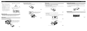
...outwards in the bracket. Fig. 11 DIN Rear-mount Installation using the top and bottom tabs. Fig. 13 Screw Dashboard or Console Factory radio mounting bracket Fig. 14 Switching the DSP setting mode This product features two operation modes: the 3-way network mode (NW) and the standard...Keeping the keys pressed against the sides of the unit, tem- Frame Fig. 12 2. Fastening the unit to the factory radio mounting bracket. (Fig. 13) (Fig. 14) Select a position where the screw holes of the bracket and the screw holes of the head unit become aligned (are correct and the system works ...
...outwards in the bracket. Fig. 11 DIN Rear-mount Installation using the top and bottom tabs. Fig. 13 Screw Dashboard or Console Factory radio mounting bracket Fig. 14 Switching the DSP setting mode This product features two operation modes: the 3-way network mode (NW) and the standard...Keeping the keys pressed against the sides of the unit, tem- Frame Fig. 12 2. Fastening the unit to the factory radio mounting bracket. (Fig. 13) (Fig. 14) Select a position where the screw holes of the bracket and the screw holes of the head unit become aligned (are correct and the system works ...

