
Other Manual
Page 1
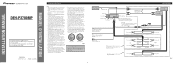
...unit is ground. If you ground the products together and the ground becomes detached, there is for the Wired Remote Control (sold separately) + Front speaker ≠ + Front speaker ≠ Right + Rear speaker ...circuit is output through a hole into the lead. The current capacity of the auto-antenna. Multi-CD player (sold separately) IP-BUS cable This product Connecting cords with RCA pin plugs (sold separately)...relay control terminal (max. 300 mA 12 V DC). INSTALLATION MANUAL OF OF DEH-P3700MP This product conforms to CEMA cord colors. Le code de couleur des câbles utilis&#...
...unit is ground. If you ground the products together and the ground becomes detached, there is for the Wired Remote Control (sold separately) + Front speaker ≠ + Front speaker ≠ Right + Rear speaker ...circuit is output through a hole into the lead. The current capacity of the auto-antenna. Multi-CD player (sold separately) IP-BUS cable This product Connecting cords with RCA pin plugs (sold separately)...relay control terminal (max. 300 mA 12 V DC). INSTALLATION MANUAL OF OF DEH-P3700MP This product conforms to CEMA cord colors. Le code de couleur des câbles utilis&#...
Other Manual
Page 4
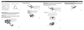
...supplied extraction keys into the dashboard, then select the appropriate tabs according to the thickness of the frame outwards in the bracket. 10 Factory radio mounting bra1c2ket 1S1crew D13ashboard or Console Fig. 8 Fig. 9 About the fixing screws for instance, near a heater outlet. • If ...For details, refer to ensure proper installation. Fig. 6 Fig. 4 DIN Rear-mount Installation using the top and bottom tabs. porarily connect the wiring to confirm that the connections are fitted), and tighten the screws at the sides of unit chassis). Remove the frame. (Fig. 7) Frame ...
...supplied extraction keys into the dashboard, then select the appropriate tabs according to the thickness of the frame outwards in the bracket. 10 Factory radio mounting bra1c2ket 1S1crew D13ashboard or Console Fig. 8 Fig. 9 About the fixing screws for instance, near a heater outlet. • If ...For details, refer to ensure proper installation. Fig. 6 Fig. 4 DIN Rear-mount Installation using the top and bottom tabs. porarily connect the wiring to confirm that the connections are fitted), and tighten the screws at the sides of unit chassis). Remove the frame. (Fig. 7) Frame ...


