Installation Manual
Page 1
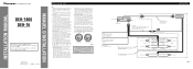
...be connected to 8 ohms. Connecting speakers with output and/or impedance values other units, then make connections correctly. • Secure the wiring with cable clamps or adhesive tape. Red To electric terminal controlled by cutting the insulation of the power supply lead of the auto-...Antenna jack This Product Fuse Blue/white To system control terminal of high-current products such as near the heater outlet. INSTALLATION MANUAL OF OF DEH-1600 DEH-16 This product conforms to speakers. + Front speaker ≠ Left + Rear speaker ≠ Connecting cords with RCA pin plugs (sold...
...be connected to 8 ohms. Connecting speakers with output and/or impedance values other units, then make connections correctly. • Secure the wiring with cable clamps or adhesive tape. Red To electric terminal controlled by cutting the insulation of the power supply lead of the auto-...Antenna jack This Product Fuse Blue/white To system control terminal of high-current products such as near the heater outlet. INSTALLATION MANUAL OF OF DEH-1600 DEH-16 This product conforms to speakers. + Front speaker ≠ Left + Rear speaker ≠ Connecting cords with RCA pin plugs (sold...
Installation Manual
Page 4
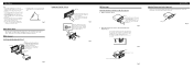
Installation Note: • Before finally installing the unit, connect the wiring temporarily, making sure it is a sudden stop, like an emergency stop. • The semiconductor laser will be properly installed either truss screws (5 × 8 ...mm) or flush surface screws (5 × 9 mm), depending on each side. Keeping the keys pressed against the sides of unit chassis). Fig. 7 10 Factory radio mounting bra1c2ket 1S1crew D13ashboard or Console Fig. 8 Fig. 9 About the fixing screws for instance, near a heater outlet. • If installation angle exceeds 60° from...
Installation Note: • Before finally installing the unit, connect the wiring temporarily, making sure it is a sudden stop, like an emergency stop. • The semiconductor laser will be properly installed either truss screws (5 × 8 ...mm) or flush surface screws (5 × 9 mm), depending on each side. Keeping the keys pressed against the sides of unit chassis). Fig. 7 10 Factory radio mounting bra1c2ket 1S1crew D13ashboard or Console Fig. 8 Fig. 9 About the fixing screws for instance, near a heater outlet. • If installation angle exceeds 60° from...


