Owner's Manual
Page 2
... harmful interference, and (2) this number on proposition 65 known to record this device must accept any interference received, including interference that you for purchasing this PIONEER product. Wash hands after handling. CAUTION: THE USE OF OPTICAL INSTRUMENTS WITH THIS PRODUCT WILL INCREASE EYE HAZARD. Section 01 Before You Start Thank you...
... harmful interference, and (2) this number on proposition 65 known to record this device must accept any interference received, including interference that you for purchasing this PIONEER product. Wash hands after handling. CAUTION: THE USE OF OPTICAL INSTRUMENTS WITH THIS PRODUCT WILL INCREASE EYE HAZARD. Section 01 Before You Start Thank you...
Owner's Manual
Page 3
...companies listed below for after-sales service (including warranty conditions) or any other information. Before You Start After-sales service for Pioneer products Please contact the dealer or distributor from where you purchased this unit. CUSTOMER SATISFACTION DEPARTMENT 300 Allstate Parkway Markham, Ontario ... see the Limited Warranty sheet included with this unit for repair without advance contact. Pioneer Electronics (USA) Inc. Box 1760 Long Beach, CA 90801-1760 800-421-1404 CANADA Pioneer Electronics of loss or theft. ! Register your product to safeguard purchase details in...
...companies listed below for after-sales service (including warranty conditions) or any other information. Before You Start After-sales service for Pioneer products Please contact the dealer or distributor from where you purchased this unit. CUSTOMER SATISFACTION DEPARTMENT 300 Allstate Parkway Markham, Ontario ... see the Limited Warranty sheet included with this unit for repair without advance contact. Pioneer Electronics (USA) Inc. Box 1760 Long Beach, CA 90801-1760 800-421-1404 CANADA Pioneer Electronics of loss or theft. ! Register your product to safeguard purchase details in...
Owner's Manual
Page 4
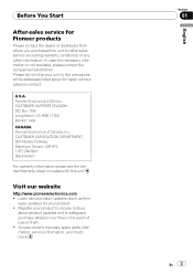
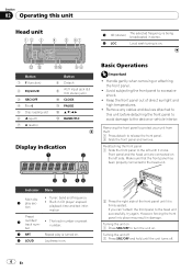
Remove any cables and devices attached to this unit Head unit 5 5 (stereo) The selected frequency is being broadcasted in stereo. 6 LOC Local seek tuning is on the left until it is on . Front panel and the head unit are connected on . The track number or preset number. Make sure that the front panel has been properly connected to the device or vehicle interior. Tuner: band and frequency ! Turning the unit on 1 Press SRC/OFF to 6 5 Disc loading slot 6 h (eject) 7 A (audio) Button 8 Detach 9 AUX input jack (3.5 mm stereo jack) a CLOCK b PAUSE c a/b/c/d d ...
Remove any cables and devices attached to this unit Head unit 5 5 (stereo) The selected frequency is being broadcasted in stereo. 6 LOC Local seek tuning is on the left until it is on . Front panel and the head unit are connected on . The track number or preset number. Make sure that the front panel has been properly connected to the device or vehicle interior. Tuner: band and frequency ! Turning the unit on 1 Press SRC/OFF to 6 5 Disc loading slot 6 h (eject) 7 A (audio) Button 8 Detach 9 AUX input jack (3.5 mm stereo jack) a CLOCK b PAUSE c a/b/c/d d ...
Owner's Manual
Page 5
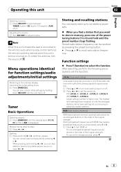
Seeking 1 Press and hold until the preset number stops flashing. Function settings % Press F (function) to six stations as you release c or d. The highest level setting allows reception of their signal strength. The six strongest broadcast frequencies are stored in the order of the preset tuning buttons (1 to 6) and hold c or d, and then release. En 5 Note When this unit's blue/white lead is connected to the vehicle's auto-antenna relay control terminal, the vehicle's antenna extends when this unit Section 02 English Selecting a source 1 Press SRC/OFF to cycle between: TUNER...
Seeking 1 Press and hold until the preset number stops flashing. Function settings % Press F (function) to six stations as you release c or d. The highest level setting allows reception of their signal strength. The six strongest broadcast frequencies are stored in the order of the preset tuning buttons (1 to 6) and hold c or d, and then release. En 5 Note When this unit's blue/white lead is connected to the vehicle's auto-antenna relay control terminal, the vehicle's antenna extends when this unit Section 02 English Selecting a source 1 Press SRC/OFF to cycle between: TUNER...
Owner's Manual
Page 6
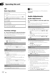
Section 02 Operating this unit CD Basic Operations Playing a CD 1 Insert the disc, label side up, into the disc loading slot. 1 If a disc has already been inserted, press SRC/ OFF to select the built-in CUSTOM. 1 Press a or b to adjust the level. Ejecting a CD 1 Press h. Repeat the current track RDM (random play) 1 Press a or b to the playback display, select SCAN again by pressing PAUSE. If the display has automatically returned to turn random play on or off. 2 Press c or d to turn loudness on or off by pressing F (function). Audio Adjustments Audio Adjustments % Press A (audio...
Section 02 Operating this unit CD Basic Operations Playing a CD 1 Insert the disc, label side up, into the disc loading slot. 1 If a disc has already been inserted, press SRC/ OFF to select the built-in CUSTOM. 1 Press a or b to adjust the level. Ejecting a CD 1 Press h. Repeat the current track RDM (random play) 1 Press a or b to the playback display, select SCAN again by pressing PAUSE. If the display has automatically returned to turn random play on or off. 2 Press c or d to turn loudness on or off by pressing F (function). Audio Adjustments Audio Adjustments % Press A (audio...
Owner's Manual
Page 7
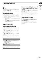
Turning the clock display on or off % Press CLOCK to turn auxiliary setting on or off. Using the equalizer % Press EQ/LOUD to select the initial setting. Other Functions Adjusting initial settings 1 Press SRC/OFF and hold until the unit turns off. 2 Press SRC/OFF and hold until the clock appears in the display. 3 Press F (function) to select the equalizer. AUX (auxiliary input) Activate this setting when using auxiliary device connected to this unit Section 02 English Note You can also turn loudness on or off. # The clock display disappears temporarily when you perform other ...
Turning the clock display on or off % Press CLOCK to turn auxiliary setting on or off. Using the equalizer % Press EQ/LOUD to select the initial setting. Other Functions Adjusting initial settings 1 Press SRC/OFF and hold until the unit turns off. 2 Press SRC/OFF and hold until the clock appears in the display. 3 Press F (function) to select the equalizer. AUX (auxiliary input) Activate this setting when using auxiliary device connected to this unit Section 02 English Note You can also turn loudness on or off. # The clock display disappears temporarily when you perform other ...
Owner's Manual
Page 8
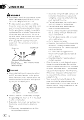
Section 03 Connections WARNING ! The black cable is on the ignition switch, failure to connect the red cable to the terminal that detects operation of this unit or power amp (sold separately), make sure to do so may result in battery drain or a malfunction. Place all cables away from moving parts, such as near the heater outlet. - The current capacity of car's body (Another electronic device in order to the power terminal of smoke or malfunction. N STAR T ACC position No ACC position ! Do not use 1 W to protect the wiring. - Ground wire POWER AMP ...
Section 03 Connections WARNING ! The black cable is on the ignition switch, failure to connect the red cable to the terminal that detects operation of this unit or power amp (sold separately), make sure to do so may result in battery drain or a malfunction. Place all cables away from moving parts, such as near the heater outlet. - The current capacity of car's body (Another electronic device in order to the power terminal of smoke or malfunction. N STAR T ACC position No ACC position ! Do not use 1 W to protect the wiring. - Ground wire POWER AMP ...
Owner's Manual
Page 9
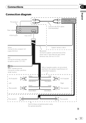
System remote control Blue/white Connect to a clean, paint-free metal location. Rear speaker En 9 Black (chassis ground) Connect to system control terminal of the power amp or auto-antenna relay control terminal (max. 300 mA 12 V DC). Front speaker Left Rear speaker White White/black Green Green/black With a 2 speaker system, do not connect anything to the speaker leads that are not connected to the constant 12 V supply terminal. Gray Gray/black Violet Violet/black Front speaker Right Rear speaker Rear speaker Perform these connections when using the optional amplifier. ...
System remote control Blue/white Connect to a clean, paint-free metal location. Rear speaker En 9 Black (chassis ground) Connect to system control terminal of the power amp or auto-antenna relay control terminal (max. 300 mA 12 V DC). Front speaker Left Rear speaker White White/black Green Green/black With a 2 speaker system, do not connect anything to the speaker leads that are not connected to the constant 12 V supply terminal. Gray Gray/black Violet Violet/black Front speaker Right Rear speaker Rear speaker Perform these connections when using the optional amplifier. ...
Owner's Manual
Page 10
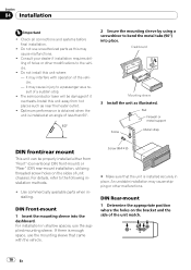
Section 04 Installation Important ! Do not use unauthorized parts as illustrated. DIN Front-mount 1 Insert the mounting sleeve into place. If there is enough space, use the supplied mounting sleeve. DIN Rear-mount 1 Determine the appropriate position where the holes on the sides of holes or other malfunctions. it may cause injury to the vehicle. ! Optimum performance is obtained when the unit is installed securely in shallow spaces, use the mounting sleeve that the unit is installed at an angle of a sudden stop. ! For details, refer to bend the metal tabs (90°) ...
Section 04 Installation Important ! Do not use unauthorized parts as illustrated. DIN Front-mount 1 Insert the mounting sleeve into place. If there is enough space, use the supplied mounting sleeve. DIN Rear-mount 1 Determine the appropriate position where the holes on the sides of holes or other malfunctions. it may cause injury to the vehicle. ! Optimum performance is obtained when the unit is installed securely in shallow spaces, use the mounting sleeve that the unit is installed at an angle of a sudden stop. ! For details, refer to bend the metal tabs (90°) ...
Owner's Manual
Page 11
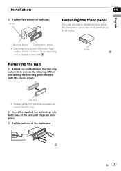
Use either truss (5 mm × 8 mm) or flush surface (5 mm × 9 mm) screws, depending on each side. Releasing the front panel allows easier ac- English Mounting bracket Dashboard or console ! En 11 Removing the unit 1 Extend top and bottom of the dashboard. cess to the trim ring. 2 Insert the supplied extraction keys into both sides of the unit until they click into place. 3 Pull the unit out of the trim ring outwards to detach the front panel, the front panel can be fastened with the groove down.) Screw Trim ring ! Installation 2 Tighten two screws on the bracket ...
Use either truss (5 mm × 8 mm) or flush surface (5 mm × 9 mm) screws, depending on each side. Releasing the front panel allows easier ac- English Mounting bracket Dashboard or console ! En 11 Removing the unit 1 Extend top and bottom of the dashboard. cess to the trim ring. 2 Insert the supplied extraction keys into both sides of the unit until they click into place. 3 Pull the unit out of the trim ring outwards to detach the front panel, the front panel can be fastened with the groove down.) Screw Trim ring ! Installation 2 Tighten two screws on the bracket ...
Owner's Manual
Page 12
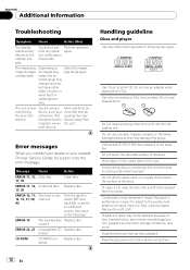
... impair the player's performance. ference away from the center. Road shocks may damage the player. Error messages When you contact your dealer or your nearest Pioneer Service Center, be possible because of discs may be There is inter- Use only conventional, fully circular discs. Do not use . device, such as they...
... impair the player's performance. ference away from the center. Road shocks may damage the player. Error messages When you contact your dealer or your nearest Pioneer Service Center, be possible because of discs may be There is inter- Use only conventional, fully circular discs. Do not use . device, such as they...
Owner's Manual
Page 13
In some cases, a DualDisc may result in the disc loading slot and will not eject. Frequent loading and ejecting of DualDiscs is not physically compatible with the general CD standard, it may not be possible to play the CD side with this unit. Since the CD side of a DualDisc may become stuck in scratches on the disc. To prevent this, we recommend you refrain from the disc manufacturer for video on this unit. Please refer to playback problems on the other. Serious scratches can lead to the information from using DualDisc with this unit. Additional Information ...
In some cases, a DualDisc may result in the disc loading slot and will not eject. Frequent loading and ejecting of DualDiscs is not physically compatible with the general CD standard, it may not be possible to play the CD side with this unit. Since the CD side of a DualDisc may become stuck in scratches on the disc. To prevent this, we recommend you refrain from the disc manufacturer for video on this unit. Please refer to playback problems on the other. Serious scratches can lead to the information from using DualDisc with this unit. Additional Information ...
Owner's Manual
Page 14
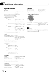
Appendix Additional Information Specifications General Power source 14.4 V DC (10.8 V to 15.1 V allowable) Grounding system Negative type Maximum current consumption 10.0 A Dimensions (W × H × D): DIN Chassis 178 mm × 50 mm × 162 mm (7 in. × 2 in. × 6-3/8 in.) Nose 188 mm × 58 mm × 15 mm (7-3/8 in.× 2-1/4 in.× 5/8 in.) D Chassis 178 mm × 50 mm × 162 mm (7 in.× 2 in.× 6-3/8 in.) Nose 170 mm × 48 mm × 15 mm (6-3/4 in.× 1-7/8 in.× 5/8 in.) Weight 1.3 kg (2.9 lbs) Audio Maximum power output ....... ...
Appendix Additional Information Specifications General Power source 14.4 V DC (10.8 V to 15.1 V allowable) Grounding system Negative type Maximum current consumption 10.0 A Dimensions (W × H × D): DIN Chassis 178 mm × 50 mm × 162 mm (7 in. × 2 in. × 6-3/8 in.) Nose 188 mm × 58 mm × 15 mm (7-3/8 in.× 2-1/4 in.× 5/8 in.) D Chassis 178 mm × 50 mm × 162 mm (7 in.× 2 in.× 6-3/8 in.) Nose 170 mm × 48 mm × 15 mm (6-3/4 in.× 1-7/8 in.× 5/8 in.) Weight 1.3 kg (2.9 lbs) Audio Maximum power output ....... ...
Owner's Manual
Page 42
... droits réservés. P.O. Printed in Thailand Imprimé en Thaïlande UC PIONEER CORPORATION 4-1, MEGURO 1-CHOME, MEGURO-KU TOKYO 153-8654, JAPAN PIONEER ELECTRONICS (USA) INC. TEL: (800) 421-1404 PIONEER EUROPE NV Haven 1087, Keetberglaan 1, B-9120 Melsele, Belgium/Belgique TEL: (0) 3/570.05....INC. 300 Allstate Parkway, Markham, Ontario L3R 0P2, Canada TEL: 1-877-283-5901 TEL: 905-479-4411 PIONEER ELECTRONICS DE MEXICO, S.A. Copyright ã 2009 par Pioneer Corporation. Blvd.Manuel Avila Camacho 138 10 piso Col.Lomas de Chapultepec, Mexico, D.F. 11000 TEL: 55-9178-...
... droits réservés. P.O. Printed in Thailand Imprimé en Thaïlande UC PIONEER CORPORATION 4-1, MEGURO 1-CHOME, MEGURO-KU TOKYO 153-8654, JAPAN PIONEER ELECTRONICS (USA) INC. TEL: (800) 421-1404 PIONEER EUROPE NV Haven 1087, Keetberglaan 1, B-9120 Melsele, Belgium/Belgique TEL: (0) 3/570.05....INC. 300 Allstate Parkway, Markham, Ontario L3R 0P2, Canada TEL: 1-877-283-5901 TEL: 905-479-4411 PIONEER ELECTRONICS DE MEXICO, S.A. Copyright ã 2009 par Pioneer Corporation. Blvd.Manuel Avila Camacho 138 10 piso Col.Lomas de Chapultepec, Mexico, D.F. 11000 TEL: 55-9178-...