
Owner's Manual
Page 5
... Language Code Chart 130 Setting the Remote Control 131 • Setting the Dipswitches • Using it as a Navigation System Remote Control Troubleshooting 133 Terms 137 Installation 139 Connecting the Units 139 • Connecting the Power Cord of AV Receiver • Connecting the Power Cord of DVD player • Connecting to a Sold...
... Language Code Chart 130 Setting the Remote Control 131 • Setting the Dipswitches • Using it as a Navigation System Remote Control Troubleshooting 133 Terms 137 Installation 139 Connecting the Units 139 • Connecting the Power Cord of AV Receiver • Connecting the Power Cord of DVD player • Connecting to a Sold...

Owner's Manual
Page 7
...not allow other hazards. 8. As with any of the display by yourself. Do not attempt to use this manual and follow the instructions carefully. 4. Installation or servicing of the vehicle's operating systems or safety features, including air bags, or (iii) impair the driver's ability to safely operate the vehicle... in an accident, your injuries can be dangerous and could expose you to the risk of electric shock or other persons to install or service your display by persons without training and experience in your vehicle's interior, the display should not divert your attention from...
...not allow other hazards. 8. As with any of the display by yourself. Do not attempt to use this manual and follow the instructions carefully. 4. Installation or servicing of the vehicle's operating systems or safety features, including air bags, or (iii) impair the driver's ability to safely operate the vehicle... in an accident, your injuries can be dangerous and could expose you to the risk of electric shock or other persons to install or service your display by persons without training and experience in your vehicle's interior, the display should not divert your attention from...

Owner's Manual
Page 8
... and found to comply with the instructions, may invalidate the user's right to provide reasonable protection against harmful interference in a residential installation. These limits are allocated for a class B digital device, pursuant to Part 15 of the "Virtual Theater", you understand the ...radio communications. This equipment generates, uses and can radiate radio frequency energy and, if not installed and used in accordance with the limits for use in a particular installation. If this equipment does cause harmful interference to radio or television reception, which the receiver ...
... and found to comply with the instructions, may invalidate the user's right to provide reasonable protection against harmful interference in a residential installation. These limits are allocated for a class B digital device, pursuant to Part 15 of the "Virtual Theater", you understand the ...radio communications. This equipment generates, uses and can radiate radio frequency energy and, if not installed and used in accordance with the limits for use in a particular installation. If this equipment does cause harmful interference to radio or television reception, which the receiver ...

Owner's Manual
Page 10
Important The serial number of this device is located on the screen. WARNING • NEVER install the display in a location that is visible to the driver. • In some countries or states the viewing of images on the enclosed warranty card. 9 ...
Important The serial number of this device is located on the screen. WARNING • NEVER install the display in a location that is visible to the driver. • In some countries or states the viewing of images on the enclosed warranty card. 9 ...

Owner's Manual
Page 22
... operate. • When the control is not to be used batteries. • In the event of battery leakage, wipe the remote control completely clean and install new batteries. • We recommended using alkaline batteries as replacements. • When disposing of the remote control and insert the batteries with governmental regulations or...
... operate. • When the control is not to be used batteries. • In the event of battery leakage, wipe the remote control completely clean and install new batteries. • We recommended using alkaline batteries as replacements. • When disposing of the remote control and insert the batteries with governmental regulations or...

Owner's Manual
Page 23
Note: • The automatic close /open mode. If the display is turned ON again (or turned to ACC), the display will be deployed automatically. * Installing the front panel will not deploy the display. In this case, press the OPEN/CLOSE button to page 120.) • When the ignition switch is ...
Note: • The automatic close /open mode. If the display is turned ON again (or turned to ACC), the display will be deployed automatically. * Installing the front panel will not deploy the display. In this case, press the OPEN/CLOSE button to page 120.) • When the ignition switch is ...

Owner's Manual
Page 140
... short-circuiting if the leads are common. • Speakers connected to this unit must be sure to disconnect the · battery cable before beginning installation. • Refer to the amp's power terminal. If the car features a glass antenna, connect to the antenna booster power supply terminal. •... connect to an external power amp's system remote control or the car's Auto-antenna relay control terminal (max. 300 mA 12 V DC). Before installing it in a recreational vehicle, truck, or bus, check the battery voltage. • To avoid shorts in the speakers catching fire, emitting smoke...
... short-circuiting if the leads are common. • Speakers connected to this unit must be sure to disconnect the · battery cable before beginning installation. • Refer to the amp's power terminal. If the car features a glass antenna, connect to the antenna booster power supply terminal. •... connect to an external power amp's system remote control or the car's Auto-antenna relay control terminal (max. 300 mA 12 V DC). Before installing it in a recreational vehicle, truck, or bus, check the battery voltage. • To avoid shorts in the speakers catching fire, emitting smoke...

Owner's Manual
Page 141
...If you are away from the ground of the unit should be different colors even if they have the same function. Installation N STAR N STAR • If this unit is installed in a vehicle that have the same function. 140 Please ground this product to another product, refer to a terminal ... ground becomes detached, there is ground. When connecting this lead separately from the vehicle for other products may be connected to the supplied Installation manuals of both products and connect cords that does not have an ACC (accessory) position on the ignition switch, the red lead of...
...If you are away from the ground of the unit should be different colors even if they have the same function. Installation N STAR N STAR • If this unit is installed in a vehicle that have the same function. 140 Please ground this product to another product, refer to a terminal ... ground becomes detached, there is ground. When connecting this lead separately from the vehicle for other products may be connected to the supplied Installation manuals of both products and connect cords that does not have an ACC (accessory) position on the ignition switch, the red lead of...

Owner's Manual
Page 142
... the parking brake switch depends on the cellular telephone. Clamp firmly with power regardless of ignition switch position. Connecting the Power Cord of AV Receiver Installation Parking brake switch Power supply side Ground side Light green Used to the power supply side of the parking brake switch. For details, consult the...
... the parking brake switch depends on the cellular telephone. Clamp firmly with power regardless of ignition switch position. Connecting the Power Cord of AV Receiver Installation Parking brake switch Power supply side Ground side Light green Used to the power supply side of the parking brake switch. For details, consult the...

Owner's Manual
Page 143
Installation This Product (AV Receiver) Antenna cable (supplied) 6 m (19 ft. 8 in.) Blue/white To system control terminal of the power amp or Autoantenna relay control terminal (max. 300 mA 12V DC). + Front speaker ≠ Left + Rear speaker ≠ White Gray White/black Gray/black Green Violet Green/black Violet/black + Front speaker ≠ Right + Rear speaker ≠ With a 2 speaker system, do not connect anything to the speaker leads that are not connected to speakers. 142
Installation This Product (AV Receiver) Antenna cable (supplied) 6 m (19 ft. 8 in.) Blue/white To system control terminal of the power amp or Autoantenna relay control terminal (max. 300 mA 12V DC). + Front speaker ≠ Left + Rear speaker ≠ White Gray White/black Gray/black Green Violet Green/black Violet/black + Front speaker ≠ Right + Rear speaker ≠ With a 2 speaker system, do not connect anything to the speaker leads that are not connected to speakers. 142

Owner's Manual
Page 144
Fuse holder 143 Connecting the Power Cord of ignition switch position. Black (ground) To vehicle (metal) body. Fuse resistor Yellow To terminal always supplied with power regardless of DVD Player Installation White (audio output (Left)) (REAR OUTPUT) Red (audio output (Right)) (REAR OUTPUT) Yellow (rear video output) (REAR VIDEO OUTPUT) Yellow (AVM output) (AVM OUTPUT) Yellow (video input) (VIDEO INPUT) 16 cm (6-1/4 in.) 16 cm (6-1/4 in.) 16 cm (6-1/4 in.) 16 cm (6-1/4 in.) 16 cm (6-1/4 in.) Orange/white To lighting switch terminal.
Fuse holder 143 Connecting the Power Cord of ignition switch position. Black (ground) To vehicle (metal) body. Fuse resistor Yellow To terminal always supplied with power regardless of DVD Player Installation White (audio output (Left)) (REAR OUTPUT) Red (audio output (Right)) (REAR OUTPUT) Yellow (rear video output) (REAR VIDEO OUTPUT) Yellow (AVM output) (AVM OUTPUT) Yellow (video input) (VIDEO INPUT) 16 cm (6-1/4 in.) 16 cm (6-1/4 in.) 16 cm (6-1/4 in.) 16 cm (6-1/4 in.) 16 cm (6-1/4 in.) Orange/white To lighting switch terminal.
Owner's Manual
Page 145
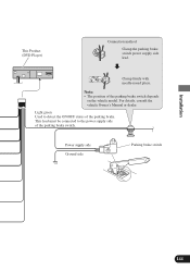
Note: • The position of the parking brake. Light green Used to the power supply side of the parking brake switch. This lead must be connected to detect the ON/OFF status of the parking brake switch depends on the vehicle model. For details, consult the vehicle Owner's Manual or dealer. Clamp firmly with needle-nosed pliers. Power supply side Ground side Parking brake switch 144 Installation This Product (DVD Player) Connection method Clamp the parking brake switch power supply side lead.
Note: • The position of the parking brake. Light green Used to the power supply side of the parking brake switch. This lead must be connected to detect the ON/OFF status of the parking brake switch depends on the vehicle model. For details, consult the vehicle Owner's Manual or dealer. Clamp firmly with needle-nosed pliers. Power supply side Ground side Parking brake switch 144 Installation This Product (DVD Player) Connection method Clamp the parking brake switch power supply side lead.

Owner's Manual
Page 146
... System remote control System remote control Front speaker Front speaker Rear speaker Rear speaker Subwoofer Subwoofer Perform these connections when using the RCA output jacks. Installation Connecting to a Sold Separately Power Amp This product can be connected to a sold separately power amp using a different amp (sold separately). 145 Power amp (sold...
... System remote control System remote control Front speaker Front speaker Rear speaker Rear speaker Subwoofer Subwoofer Perform these connections when using the RCA output jacks. Installation Connecting to a Sold Separately Power Amp This product can be connected to a sold separately power amp using a different amp (sold separately). 145 Power amp (sold...

Owner's Manual
Page 147
Speaker Input Jack Connection This product also can be connected to a car stereo without RCA output jacks by using the speaker input jack. This Product (AV Receiver) Speaker input terminal Gray Gray/black White White/black Car stereo with speaker output jacks. + Right ≠ Front speaker + Left ≠ Installation 146
Speaker Input Jack Connection This product also can be connected to a car stereo without RCA output jacks by using the speaker input jack. This Product (AV Receiver) Speaker input terminal Gray Gray/black White White/black Car stereo with speaker output jacks. + Right ≠ Front speaker + Left ≠ Installation 146

Owner's Manual
Page 148
Connecting the System Installation This product (AV Receiver) Green Red (Right) White (Left) Yellow 20 pin RGB cable (supplied) Red Yellow Red Blue IP-BUS cable (supplied with the TV tuner) Black Blue Hide-away TV Tuner (e.g. GEX-P7000TV) (sold separately) 20 pin cable (supplied with the TV tuner) 6m (19 ft. 8 in.) FM MODULATOR IP-BUS MAIN UNIT IP-BUS AV MASTER RCA cable (sold separately) Red Gray Green AV cable (supplied) 147
Connecting the System Installation This product (AV Receiver) Green Red (Right) White (Left) Yellow 20 pin RGB cable (supplied) Red Yellow Red Blue IP-BUS cable (supplied with the TV tuner) Black Blue Hide-away TV Tuner (e.g. GEX-P7000TV) (sold separately) 20 pin cable (supplied with the TV tuner) 6m (19 ft. 8 in.) FM MODULATOR IP-BUS MAIN UNIT IP-BUS AV MASTER RCA cable (sold separately) Red Gray Green AV cable (supplied) 147

Owner's Manual
Page 149
Installation 1.5 m (4 ft. 11 in.) Green Navigation Unit (sold separately) To video output To audio outputs RCA cables (sold separately) 3m (9 ft. 10 in.) Blue This product (DVD Player) 40 cm (1 ft. 4 in.) RCA cable (supplied) 6m (19 ft. 8 in.) Blue 40 cm (1 ft. 4 in .) Yellow (AVM OUTPUT) 20 pin cable Red (supplied) 148 IP-BUS cable (supplied) 3m (9 ft. 10 in.) Gray Green 3 m (9 ft. 10 in.) 16 cm (6-1/4 in .) Not used. Voice guidance speaker (supplied) Multi-CD player (sold separately) Yellow/black To Yellow/black lead (GUIDE ON) on the navigation unit.
Installation 1.5 m (4 ft. 11 in.) Green Navigation Unit (sold separately) To video output To audio outputs RCA cables (sold separately) 3m (9 ft. 10 in.) Blue This product (DVD Player) 40 cm (1 ft. 4 in.) RCA cable (supplied) 6m (19 ft. 8 in.) Blue 40 cm (1 ft. 4 in .) Yellow (AVM OUTPUT) 20 pin cable Red (supplied) 148 IP-BUS cable (supplied) 3m (9 ft. 10 in.) Gray Green 3 m (9 ft. 10 in.) 16 cm (6-1/4 in .) Not used. Voice guidance speaker (supplied) Multi-CD player (sold separately) Yellow/black To Yellow/black lead (GUIDE ON) on the navigation unit.

Owner's Manual
Page 150
...(sold separately). If you can also watch the Video or DVD while Driving. When connecting the Display with RCA input jacks WARNING • NEVER install the display in a location that enables the Driver to watch the external video component's picture. To audio inputs To video input Display with RCA input... jacks to Rear AV output, you wish to enjoy DVD viewing on the AV Receiver. Installation VIDEO Input/Output Connection of AV Receiver It is possible to use an external video component by connecting it to the AV input on the...
...(sold separately). If you can also watch the Video or DVD while Driving. When connecting the Display with RCA input jacks WARNING • NEVER install the display in a location that enables the Driver to watch the external video component's picture. To audio inputs To video input Display with RCA input... jacks to Rear AV output, you wish to enjoy DVD viewing on the AV Receiver. Installation VIDEO Input/Output Connection of AV Receiver It is possible to use an external video component by connecting it to the AV input on the...

Owner's Manual
Page 151
...) 16 cm (6-1/4 in.) 16 cm (6-1/4 in.) 16 cm (6-1/4 in a location that enables the Driver to watch the DVD or Video CD while Driving. Installation Rear Video Output of DVD Player DVD Player's rear video output is for connection of a display to enable passengers in the rear seats to watch... the DVD or Video CD. WARNING • NEVER install the display in .) White (audio output (Left)) Red (audio output (Right)) RCA cable (sold separately) RCA cable (sold separately) To video input To...
...) 16 cm (6-1/4 in.) 16 cm (6-1/4 in.) 16 cm (6-1/4 in a location that enables the Driver to watch the DVD or Video CD while Driving. Installation Rear Video Output of DVD Player DVD Player's rear video output is for connection of a display to enable passengers in the rear seats to watch... the DVD or Video CD. WARNING • NEVER install the display in .) White (audio output (Left)) Red (audio output (Right)) RCA cable (sold separately) RCA cable (sold separately) To video input To...

Owner's Manual
Page 152
... or fittings. • Do not mount the AV Receiver near the doors, where rainwater might not give its optimum performance. Installation Installation Note: • Before finally installing the unit, connect the wiring temporarily, making sure it does not obstruct seat movement. Velcro tape (20 × 90 mm...any mounting holes always check behind where you want to 2.5 mm (1/8 in.) diameter holes. 7 Mounting with the unit to ensure proper installation. Route all connected up properly, and the unit and the system work properly. • Use only the parts included with Velcro Tape...
... or fittings. • Do not mount the AV Receiver near the doors, where rainwater might not give its optimum performance. Installation Installation Note: • Before finally installing the unit, connect the wiring temporarily, making sure it does not obstruct seat movement. Velcro tape (20 × 90 mm...any mounting holes always check behind where you want to 2.5 mm (1/8 in.) diameter holes. 7 Mounting with the unit to ensure proper installation. Route all connected up properly, and the unit and the system work properly. • Use only the parts included with Velcro Tape...

Owner's Manual
Page 153
... remove the frame. (When reattaching the frame, point the side with the rubber bush 1. Install side brackets. Installation Installing the DVD Player (DIN Front/Rear-mount) DVD Player can be properly installed either from "Front" (conventional DIN Front-mount) or "Rear" (DIN Rear-mount installation, utilizing threaded screw holes at the sides of unit chassis).
... remove the frame. (When reattaching the frame, point the side with the rubber bush 1. Install side brackets. Installation Installing the DVD Player (DIN Front/Rear-mount) DVD Player can be properly installed either from "Front" (conventional DIN Front-mount) or "Rear" (DIN Rear-mount installation, utilizing threaded screw holes at the sides of unit chassis).


