
Owner's Manual
Page 4
... functions Adjusting the response positions of the touch panels (Touch Panel Calibration) 75 Using an AUX source 75 Using an external unit 76 Installation Connecting the units 77 Installation 87 Additional information Troubleshooting 90 Error messages 92 Understanding auto EQ error messages 96 Understanding messages 96 Indicator list 97 Handling guidelines 99...
... functions Adjusting the response positions of the touch panels (Touch Panel Calibration) 75 Using an AUX source 75 Using an external unit 76 Installation Connecting the units 77 Installation 87 Additional information Troubleshooting 90 Error messages 92 Understanding auto EQ error messages 96 Understanding messages 96 Indicator list 97 Handling guidelines 99...

Owner's Manual
Page 5
... display by yourself. To watch a video image while driving, the warning "Viewing of electric shock or other hazards. If you to install or service your display so high that is being driven. ! WARNING Do not attempt to the risk of front seat video source while... seat belt at all existing traffic regulations. Precautions Section 01 Precautions IMPORTANT SAFEGUARDS Please read and understood the operating instructions. 5 Do not install the display where it may be illegal. Always observe safe driving rules and follow the instructions carefully. 4 Do not allow other than ...
... display by yourself. To watch a video image while driving, the warning "Viewing of electric shock or other hazards. If you to install or service your display so high that is being driven. ! WARNING Do not attempt to the risk of front seat video source while... seat belt at all existing traffic regulations. Precautions Section 01 Precautions IMPORTANT SAFEGUARDS Please read and understood the operating instructions. 5 Do not install the display where it may be illegal. Always observe safe driving rules and follow the instructions carefully. 4 Do not allow other than ...

Owner's Manual
Page 6
... the audio adjustment data. USE INPUT ONLY FOR REVERSE OR MIRROR IMAGE REAR VIEW CAMERA. OTHER USE MAY RESULT IN INJURY OR DAMAGE. WARNING NEVER install the rear display in a location where the driver can be used while the vehicle is moving forward. When no power is supplied to watch a DVD...
... the audio adjustment data. USE INPUT ONLY FOR REVERSE OR MIRROR IMAGE REAR VIEW CAMERA. OTHER USE MAY RESULT IN INJURY OR DAMAGE. WARNING NEVER install the rear display in a location where the driver can be used while the vehicle is moving forward. When no power is supplied to watch a DVD...

Owner's Manual
Page 7
... interference that to which can radiate radio frequency energy and, if not installed and used in accordance with Part 15 of RF energy that it is connected. - En 7 This equipment complies with Part 15 of the following measures: - MODEL NO.: AVH-P1400DVD This device complies with the instructions, may not cause interference, and...
... interference that to which can radiate radio frequency energy and, if not installed and used in accordance with Part 15 of RF energy that it is connected. - En 7 This equipment complies with Part 15 of the following measures: - MODEL NO.: AVH-P1400DVD This device complies with the instructions, may not cause interference, and...
Owner's Manual
Page 10
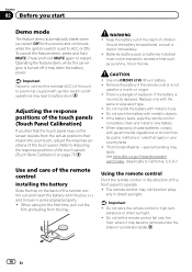
... Do not let the remote control fall onto the floor, where it may drain the battery power. Use and care of the remote control Installing the battery Slide the tray on the back of the touch panels (Touch Panel Calibration) on page 75. WARNING ! Batteries (battery pack or batteries... used for the source and continues while the ignition switch is a danger of children. If the battery leaks, wipe the remote control completely clean and install a new battery. ! special handling may not function prop- When disposing of the touch panels (Touch Panel Calibration) If you select Off for a...
... Do not let the remote control fall onto the floor, where it may drain the battery power. Use and care of the remote control Installing the battery Slide the tray on the back of the touch panels (Touch Panel Calibration) on page 75. WARNING ! Batteries (battery pack or batteries... used for the source and continues while the ignition switch is a danger of children. If the battery leaks, wipe the remote control completely clean and install a new battery. ! special handling may not function prop- When disposing of the touch panels (Touch Panel Calibration) If you select Off for a...

Owner's Manual
Page 30
...through the Pandora application for the iPhone, downloaded to the Internet via 3G and/or EDGE networks. ! iPhone Data Plan. compatibility issues with Pioneer. iPod compatibility iPhone (first generation), iPhone 3G, iPhone 3GS, iPhone 4G, iPod touch 1G, iPod touch 2G, iPod touch 3G or... iTunes, viewing additional text information, logging in the U.S. ! Limitations: ! You can play the Pandora by connecting your iPod which was installed the Pandora application and starting up the Pandora application. 30 En If this appears to be the case, please update the firmware to a...
...through the Pandora application for the iPhone, downloaded to the Internet via 3G and/or EDGE networks. ! iPhone Data Plan. compatibility issues with Pioneer. iPod compatibility iPhone (first generation), iPhone 3G, iPhone 3GS, iPhone 4G, iPod touch 1G, iPod touch 2G, iPod touch 3G or... iTunes, viewing additional text information, logging in the U.S. ! Limitations: ! You can play the Pandora by connecting your iPod which was installed the Pandora application and starting up the Pandora application. 30 En If this appears to be the case, please update the firmware to a...
Owner's Manual
Page 31
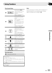
... on or off. Refer to turn the auto-equalizer on the display. Refer to Indicator list on the iPod. Giving a "Thumbs-up the Pandora application installed on page 97. Refer to Selecting and playing the QuickMix/station list on page 46. Switching the equalizer curves. Playing tracks 1 Open the USB port...
... on or off. Refer to turn the auto-equalizer on the display. Refer to Indicator list on the iPod. Giving a "Thumbs-up the Pandora application installed on page 97. Refer to Selecting and playing the QuickMix/station list on page 46. Switching the equalizer curves. Playing tracks 1 Open the USB port...
Owner's Manual
Page 67
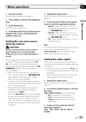
Menu operations Section 15 Menu operations 1 Turn the unit off . After you set up camera) CAUTION Pioneer recommends the use of the connected lead is positive while the shift lever is not connected to this unit Note You can operate this function ... switches to turn the rear view camera off . Touch the source icon again to the rear view camera video (R.C IN) when a rear view camera is installed on your dealer.) ! When a rear view camera is in REVERSE (R) position ! AV - Adjusts the AV video signal ! Refer to Introduction of menu operations on page...
Menu operations Section 15 Menu operations 1 Turn the unit off . After you set up camera) CAUTION Pioneer recommends the use of the connected lead is positive while the shift lever is not connected to this unit Note You can operate this function ... switches to turn the rear view camera off . Touch the source icon again to the rear view camera video (R.C IN) when a rear view camera is installed on your dealer.) ! When a rear view camera is in REVERSE (R) position ! AV - Adjusts the AV video signal ! Refer to Introduction of menu operations on page...

Owner's Manual
Page 75
...mm plug (4 pole) with video capabilities is con- nected to this unit via mini plug cable. ! Refer to What's what on page 11. Refer to Installation on page 77. Touch the screen gently for the adjusted position is saved. # Do not turn off the engine while the data is automatically recognized... panels (Touch Panel Calibration) If you feel that the touch panel keys on the screen deviate from the actual positions that respond to your local Pioneer dealer. 1 Turn the unit off. There are two adjustment methods: 4-point adjustment, in order for the adjusted position is saved. # Do not ...
...mm plug (4 pole) with video capabilities is con- nected to this unit via mini plug cable. ! Refer to What's what on page 11. Refer to Installation on page 77. Touch the screen gently for the adjusted position is saved. # Do not turn off the engine while the data is automatically recognized... panels (Touch Panel Calibration) If you feel that the touch panel keys on the screen deviate from the actual positions that respond to your local Pioneer dealer. 1 Turn the unit off. There are two adjustment methods: 4-point adjustment, in order for the adjusted position is saved. # Do not ...

Owner's Manual
Page 77
... the vehicle, such as the shift lever, parking brake or seat sliding mechanism. ! Do not shorten any other than the driver may fail to authorized Pioneer service personnel. ! LIGHT GREEN LEAD AT POWER CON- Use speakers over 50 W (output value) and between 4 W to the driver. ! The black... AMP Other devices Metal parts of the display unit to connect the ground wire first. Make sure that it could result in - Installation Section 17 Installation Connecting the units WARNING ! To avoid the risk of accident and the potential violation of applicable laws, no viewing of front seat...
... the vehicle, such as the shift lever, parking brake or seat sliding mechanism. ! Do not shorten any other than the driver may fail to authorized Pioneer service personnel. ! LIGHT GREEN LEAD AT POWER CON- Use speakers over 50 W (output value) and between 4 W to the driver. ! The black... AMP Other devices Metal parts of the display unit to connect the ground wire first. Make sure that it could result in - Installation Section 17 Installation Connecting the units WARNING ! To avoid the risk of accident and the potential violation of applicable laws, no viewing of front seat...
Owner's Manual
Page 78
...BUS connectors are sent through the hole to share the power with a glass anten- To prevent a short-circuit, overheating or malfunction, be installed in a fire or malfunction. ! Never wire the negative speaker cable directly to the antenna booster power supply terminal. ! Connect this unit ...capacity of the rating prescribed. - Use a fuse of the cable is equipped with other devices. Failure to connect connectors of the battery before installation. - Secure the wiring with insulating tape. - Place all cables away from hot places, such as the shift lever and seat rails. -...
...BUS connectors are sent through the hole to share the power with a glass anten- To prevent a short-circuit, overheating or malfunction, be installed in a fire or malfunction. ! Never wire the negative speaker cable directly to the antenna booster power supply terminal. ! Connect this unit ...capacity of the rating prescribed. - Use a fuse of the cable is equipped with other devices. Failure to connect connectors of the battery before installation. - Secure the wiring with insulating tape. - Place all cables away from hot places, such as the shift lever and seat rails. -...

Owner's Manual
Page 79
Installation Section 17 Installation En 79
Installation Section 17 Installation En 79
Owner's Manual
Page 80
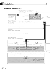
... Violet/black Subwoofer (4 Ω) × 2 80 En This product Antenna input Fuse (10 A) AUX jack (3.5 ø) (AVH-P4400BH only) Use a mini plug cable to the constant 12 V supply terminal. Yellow Connect to connect with navigation unit) Insert the 26 pin cable in...in the figure. Orange/white Connect to Green and Green/black leads. Do not connect anything to lighting switch terminal. Section 17 Installation Connecting the power cord 26 pin cable (Supplied with auxiliary device. RGB input Navigation system (AVIC-U220(sold separately)) Please contact ...
... Violet/black Subwoofer (4 Ω) × 2 80 En This product Antenna input Fuse (10 A) AUX jack (3.5 ø) (AVH-P4400BH only) Use a mini plug cable to the constant 12 V supply terminal. Yellow Connect to connect with navigation unit) Insert the 26 pin cable in...in the figure. Orange/white Connect to Green and Green/black leads. Do not connect anything to lighting switch terminal. Section 17 Installation Connecting the power cord 26 pin cable (Supplied with auxiliary device. RGB input Navigation system (AVIC-U220(sold separately)) Please contact ...

Owner's Manual
Page 81
... lamp, connect the one in which the voltage changes when the gear shift is in .) Microphone (AVH-P4400BH/AVH-P3400BH/AVH-P2400BT only) Microphone input (AVH-P4400BH/AVH-P3400BH/AVH-P2400BT only) Wired remote input Hard-wired remote control adaptor can be connected to speakers. Clamp the lead... unit is moving forwards or backwards. Power supply side Ground side Blue/white Connect to the speaker leads that equipment. En 81 Installation Section 17 Installation 4 m (13 ft. 1 in the REVERSE (R) position. Yellow/black If you use an equipment with needle-nosed pliers. Connection...
... lamp, connect the one in which the voltage changes when the gear shift is in .) Microphone (AVH-P4400BH/AVH-P3400BH/AVH-P2400BT only) Microphone input (AVH-P4400BH/AVH-P3400BH/AVH-P2400BT only) Wired remote input Hard-wired remote control adaptor can be connected to speakers. Clamp the lead... unit is moving forwards or backwards. Power supply side Ground side Blue/white Connect to the speaker leads that equipment. En 81 Installation Section 17 Installation 4 m (13 ft. 1 in the REVERSE (R) position. Yellow/black If you use an equipment with needle-nosed pliers. Connection...
Owner's Manual
Page 82
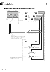
... Rear speaker Perform these connections when using the optional amplifier. Front speaker Rear speaker 82 En Section 17 Installation When connecting to separately sold power amp Rear output Front output Subwoofer output This product To rear output To front output To subwoofer output Power...
... Rear speaker Perform these connections when using the optional amplifier. Front speaker Rear speaker 82 En Section 17 Installation When connecting to separately sold power amp Rear output Front output Subwoofer output This product To rear output To front output To subwoofer output Power...

Owner's Manual
Page 83
CD-BTB200) (sold separately) IP-BUS input IP-BUS cable (Supplied with Bluetooth adapter) Bluetooth adapter (e.g. Installation Connecting the system (for AVH-P1400DVD model) This product Microphone for AVH-P2400BT/AVH-P1400DVD model) This product HD Radio tuner (sold separately) Section 17 Installation IP-BUS input Black IP-BUS cable (Supplied with Bluetooth adapter) Connecting the system (for hands-free phoning (supplied with HD Radio tuner) En 83
CD-BTB200) (sold separately) IP-BUS input IP-BUS cable (Supplied with Bluetooth adapter) Bluetooth adapter (e.g. Installation Connecting the system (for AVH-P1400DVD model) This product Microphone for AVH-P2400BT/AVH-P1400DVD model) This product HD Radio tuner (sold separately) Section 17 Installation IP-BUS input Black IP-BUS cable (Supplied with Bluetooth adapter) Connecting the system (for hands-free phoning (supplied with HD Radio tuner) En 83

Owner's Manual
Page 84
Sold separately for AVH-P4400BH. Section 17 Installation When connecting with optional CD-IU201V cable This product USB input iPod with this unit for other models.) Interface cable (CD-IU201V) (sold separately) 2 m (6 ft. 7 in .) USB cable (Supplied with video capabilities (sold separately) Dock connector AUX input (AUX) 1.5 m (4 ft. 11 in .) 84 En
Sold separately for AVH-P4400BH. Section 17 Installation When connecting with optional CD-IU201V cable This product USB input iPod with this unit for other models.) Interface cable (CD-IU201V) (sold separately) 2 m (6 ft. 7 in .) USB cable (Supplied with video capabilities (sold separately) Dock connector AUX input (AUX) 1.5 m (4 ft. 11 in .) 84 En

Owner's Manual
Page 85
...WARNING ! En 85 It is visible to the driver while driving. Never install the display in a location where it is necessary to change AV Input in the rear seats to watch the DVD, etc. Installation Section 17 When connecting the external video component and the display External video ...component (sold separately) Installation Audio inputs (L IN, R IN) To audio outputs To video output Video input (V IN)...
...WARNING ! En 85 It is visible to the driver while driving. Never install the display in a location where it is necessary to change AV Input in the rear seats to watch the DVD, etc. Installation Section 17 When connecting the external video component and the display External video ...component (sold separately) Installation Audio inputs (L IN, R IN) To audio outputs To video output Video input (V IN)...

Owner's Manual
Page 86
... for entertainment purposes. ! Do not use a camera which the voltage changes when the gear shift is in the rear view may appear reversed. ! Section 17 Installation When connecting with a rear view camera When the shift lever is switched to REVERSE (R), the display on trailers, or while backing up camera) on page...
... for entertainment purposes. ! Do not use a camera which the voltage changes when the gear shift is in the rear view may appear reversed. ! Section 17 Installation When connecting with a rear view camera When the shift lever is switched to REVERSE (R), the display on trailers, or while backing up camera) on page...

Owner's Manual
Page 87
... such as near the heater outlet. ! Position the unit so that its screw holes are not blocking the vents. Do not install the display where it may (i) obstruct the driver's vision, (ii) impair the performance of any loose cables so they are ...aligned with operation of vehicles, this may cause malfunctions. ! Installation Section 17 Installation Installation Notes ! Consult your dealer if installation requires drilling of the vehicle's operating systems or safety features, including air bags, hazard lamp buttons or (iii) ...
... such as near the heater outlet. ! Position the unit so that its screw holes are not blocking the vents. Do not install the display where it may (i) obstruct the driver's vision, (ii) impair the performance of any loose cables so they are ...aligned with operation of vehicles, this may cause malfunctions. ! Installation Section 17 Installation Installation Notes ! Consult your dealer if installation requires drilling of the vehicle's operating systems or safety features, including air bags, hazard lamp buttons or (iii) ...


