
Owner's Manual
Page 1
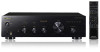
Operating Instructions Mode d'emploi Integrated Amplifier Amplificateur Intégré
Operating Instructions Mode d'emploi Integrated Amplifier Amplificateur Intégré
Owner's Manual
Page 2
...-4-2-2-2a*_A1_En D3-4-2-1-3_A1_En WARNING Before plugging in for example, when on the rear panel. D3-4-2-1-7a_A1_En VENTILATION CAUTION When installing this unit will be disconnected by qualified service personnel. To prevent fire hazard, the openings should be used meets the required voltage (e.g., 230 V or 120 V) written on vacation). NO USER-SERVICEABLE PARTS INSIDE. To prevent a fire or shock...
...-4-2-2-2a*_A1_En D3-4-2-1-3_A1_En WARNING Before plugging in for example, when on the rear panel. D3-4-2-1-7a_A1_En VENTILATION CAUTION When installing this unit will be disconnected by qualified service personnel. To prevent fire hazard, the openings should be used meets the required voltage (e.g., 230 V or 120 V) written on vacation). NO USER-SERVICEABLE PARTS INSIDE. To prevent a fire or shock...
Owner's Manual
Page 3
... power cord when your equipment by the plug. To prevent electromagnetic interference with the product may expose you . • Use caution or temporarily discontinue use shielded cables and connectors for even during the warranty period. Product Name: Integrated Amplifier Model Number: A-20 Responsible Party Name: PIONEER ELECTRONICS (USA) INC. DOMINGUEZ ST. BE SURE TO OBSERVE THE FOLLOWING GUIDELINES: • Do not turn...
... power cord when your equipment by the plug. To prevent electromagnetic interference with the product may expose you . • Use caution or temporarily discontinue use shielded cables and connectors for even during the warranty period. Product Name: Integrated Amplifier Model Number: A-20 Responsible Party Name: PIONEER ELECTRONICS (USA) INC. DOMINGUEZ ST. BE SURE TO OBSERVE THE FOLLOWING GUIDELINES: • Do not turn...
Owner's Manual
Page 4
... radiate radio frequency energy and, if not installed and used , use this Pioneer product. A grounding type plug has two blades and a third grounding prong. Increase the separation between the equipment and receiver. - Install in the remote control . . . . . .5 Using the remote control 5 Installing the amplifier 5 02 Connecting up Making cable connections 6 About "Bi-wiring 6 Connecting speaker cables 7 Connecting audio cables 7 Using centralized control with dry cloth. 7) Do not block any ventilation openings. 1) Read these instructions. 2) Keep these operating instructions so...
... radiate radio frequency energy and, if not installed and used , use this Pioneer product. A grounding type plug has two blades and a third grounding prong. Increase the separation between the equipment and receiver. - Install in the remote control . . . . . .5 Using the remote control 5 Installing the amplifier 5 02 Connecting up Making cable connections 6 About "Bi-wiring 6 Connecting speaker cables 7 Connecting audio cables 7 Using centralized control with dry cloth. 7) Do not block any ventilation openings. 1) Read these instructions. 2) Keep these operating instructions so...
Owner's Manual
Page 5
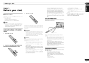
...remote control, set them in the Operating Instructions may have different voltages, even if they are very dusty - Note • Illustrations featured in the proper direction, as inside of about 7 m at an angle of the case, then insert new batteries. Also, do not plan to use the remote control... the operating range of the remote. Loading the batteries in extremely hot or cold areas - It can cause batteries to damage the springs on a sofa or other movement - Installing the amplifier When installing this unit. • Replace the batteries when you check product operation and ...
...remote control, set them in the Operating Instructions may have different voltages, even if they are very dusty - Note • Illustrations featured in the proper direction, as inside of about 7 m at an angle of the case, then insert new batteries. Also, do not plan to use the remote control... the operating range of the remote. Loading the batteries in extremely hot or cold areas - It can cause batteries to damage the springs on a sofa or other movement - Installing the amplifier When installing this unit. • Replace the batteries when you check product operation and ...
Owner's Manual
Page 6
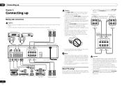
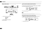
... LOW LOW This unit's rear panel R L R L This unit's rear panel L RL R R LR LR L RLRL Power cord Turntable OUTPUT L L R R Tuner L R R AUDIO OUTPUT L iPod Music> Extras> Settings> Shuffle Songs Backlight MENU iPod dock, etc PLAY REC L L L R R R CD recorder or tape deck Right Left Speaker system A • If your speakers or other devices. • The unit's PHONO (MM) terminals are designed to be sure that both the SPEAKERS A button and SPEAKERS B button are set to bend the cables...
... LOW LOW This unit's rear panel R L R L This unit's rear panel L RL R R LR LR L RLRL Power cord Turntable OUTPUT L L R R Tuner L R R AUDIO OUTPUT L iPod Music> Extras> Settings> Shuffle Songs Backlight MENU iPod dock, etc PLAY REC L L L R R R CD recorder or tape deck Right Left Speaker system A • If your speakers or other devices. • The unit's PHONO (MM) terminals are designed to be sure that both the SPEAKERS A button and SPEAKERS B button are set to bend the cables...

Owner's Manual
Page 7
... Pioneer components equipped with a remote sensor, or installed in places where the component's remote sensor cannot be lost even if the power cord is automatically disabled). 7 En Caution • When using both sets of terminals, the connected speakers should have nominal impedance between 4 Ω and 16 Ω. When using only one set of speaker terminals (SPEAKERS A or SPEAKERS B), or when utilizing bi-wiring connections, the speaker used to use speaker cables terminated with CONTROL IN/ OUT jacks A-20 Plugging...
... Pioneer components equipped with a remote sensor, or installed in places where the component's remote sensor cannot be lost even if the power cord is automatically disabled). 7 En Caution • When using both sets of terminals, the connected speakers should have nominal impedance between 4 Ω and 16 Ω. When using only one set of speaker terminals (SPEAKERS A or SPEAKERS B), or when utilizing bi-wiring connections, the speaker used to use speaker cables terminated with CONTROL IN/ OUT jacks A-20 Plugging...
Owner's Manual
Page 8
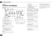
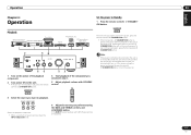
... Auto Power Down (APD) function is on, the indicator lights green (page 12). 3 SPEAKERS A button/indicator Use this position. • This button does not operate when the DIRECT button is in the on position. 12 VOLUME control Use to adjust the volume level. (Also allows adjustment of the headphone sound volume.) 13 INPUT SELECTOR knob/indicators Turn the knob clockwise or counterclockwise so that the indicator lights for the input source selected with the BASS, TREBLE, BALANCE, and LOUDNESS controls. 9 BASS tone control Use...
... Auto Power Down (APD) function is on, the indicator lights green (page 12). 3 SPEAKERS A button/indicator Use this position. • This button does not operate when the DIRECT button is in the on position. 12 VOLUME control Use to adjust the volume level. (Also allows adjustment of the headphone sound volume.) 13 INPUT SELECTOR knob/indicators Turn the knob clockwise or counterclockwise so that the indicator lights for the input source selected with the BASS, TREBLE, BALANCE, and LOUDNESS controls. 9 BASS tone control Use...

Owner's Manual
Page 9
... Español Controls and displays 03 Rear panel See pages 6 to 7 for details regarding connections. 1 2 23 24 25 6 28 120 122 7 9 11 13 1 GND (Turntable ground) terminal This ground terminal is designed to help reduce noise when a turntable is not a safety ground. 2 SPEAKERS A terminals (Right channel) 3 SPEAKERS B terminals (Right channel) 4 SPEAKERS B terminals (Left channel) 5 SPEAKERS A terminals (Left channel) 6 Power cord 7 PHONO (MM) IN terminals 8 TUNER IN terminals...
... Español Controls and displays 03 Rear panel See pages 6 to 7 for details regarding connections. 1 2 23 24 25 6 28 120 122 7 9 11 13 1 GND (Turntable ground) terminal This ground terminal is designed to help reduce noise when a turntable is not a safety ground. 2 SPEAKERS A terminals (Right channel) 3 SPEAKERS B terminals (Right channel) 4 SPEAKERS B terminals (Left channel) 5 SPEAKERS A terminals (Left channel) 6 Power cord 7 PHONO (MM) IN terminals 8 TUNER IN terminals...
Owner's Manual
Page 10
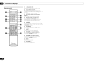
... sound. 11 VOLUME +/- 03 Controls and displays Remote control 1 5 2 6 7 3 8 4 9 10 3 11 3 4 1 STANDBY/ON Switches the amplifier between standby and on the PD-D6/PD-D6MK2/PD-D9/PD-D9MK2 models.) 5 DIMMER This button allows the illumination of the unit's front panel indicators to be set in three levels (does not affect the STANDBY indicator). 6 LOUDNESS Use to select an input source. These select the component connected to the corresponding input on the rear panel. 3 NETWORK AUDIO PLAYER control buttons Use...
... sound. 11 VOLUME +/- 03 Controls and displays Remote control 1 5 2 6 7 3 8 4 9 10 3 11 3 4 1 STANDBY/ON Switches the amplifier between standby and on the PD-D6/PD-D6MK2/PD-D9/PD-D9MK2 models.) 5 DIMMER This button allows the illumination of the unit's front panel indicators to be set in three levels (does not affect the STANDBY indicator). 6 LOUDNESS Use to select an input source. These select the component connected to the corresponding input on the rear panel. 3 NETWORK AUDIO PLAYER control buttons Use...
Owner's Manual
Page 11
... power cord is disconnected when the unit is off . If the DIRECT button has been set to your preference using the BASS and TREBLE controls, and LOUDNESS button. Select the playback component. • When using the front panel controls, rotate the INPUT SELECTOR knob. 6 Adjust the tone to ON, these controls are disabled. Operation Chapter 4: Operation Set the power to turn the power on the power, press the remote control's STANDBY/ON button. • If the front panel's STANDBY/ON button...
... power cord is disconnected when the unit is off . If the DIRECT button has been set to your preference using the BASS and TREBLE controls, and LOUDNESS button. Select the playback component. • When using the front panel controls, rotate the INPUT SELECTOR knob. 6 Adjust the tone to ON, these controls are disabled. Operation Chapter 4: Operation Set the power to turn the power on the power, press the remote control's STANDBY/ON button. • If the front panel's STANDBY/ON button...
Owner's Manual
Page 12
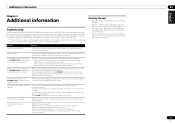
... Operation Making an audio recording You can make an audio recording from operating. Press the buttons again to the amplifier. When this condition is set, if no input signal is ON, hold the front-panel's DIRECT button and SPEAKERS A button depressed simultaneously for five seconds. 2 Turn power ON to record. 2 Start recording, then start playback of the source component. Note Depending on the unit's front panel will automatically enter standby...
... Operation Making an audio recording You can make an audio recording from operating. Press the buttons again to the amplifier. When this condition is set, if no input signal is ON, hold the front-panel's DIRECT button and SPEAKERS A button depressed simultaneously for five seconds. 2 Turn power ON to record. 2 Start recording, then start playback of the source component. Note Depending on the unit's front panel will automatically enter standby...
Owner's Manual
Page 13
... repair work. • If the unit does not operate normally due to turn on one component connected improperly? If the trouble cannot be rectified even after exercising the checks listed below . When power is turned on again without being used. Can't operate the remote control. •Replace the battery (page 5). •Operate within 7 m, 30 ºof the rear panel? Confirm correct connections (page 7). No sound is output when a function is •A connection cable...
... repair work. • If the unit does not operate normally due to turn on one component connected improperly? If the trouble cannot be rectified even after exercising the checks listed below . When power is turned on again without being used. Can't operate the remote control. •Replace the battery (page 5). •Operate within 7 m, 30 ºof the rear panel? Confirm correct connections (page 7). No sound is output when a function is •A connection cable...

Owner's Manual
Page 14
...; Tone control (When VOLUME is set to -30 dB) Bass 10 dB (100 Hz) Treble 10 dB (10 kHz) • Signal-to-Noise Ratio (IHF SHORTED, A-NETWORK) SACD/CD, NETWORK, TUNER, AUX, RECORDER 105 dB* PHONO (MM, 2.8 mV input 77 dB* * Measured with DIRECT button switched on. • Speaker load impedance A, B 4 Ω to 16 Ω A+B 8 Ω to 32 Ω Bi-wiring 4 Ω to 16 Ω Miscellaneous Power requirements...
...; Tone control (When VOLUME is set to -30 dB) Bass 10 dB (100 Hz) Treble 10 dB (10 kHz) • Signal-to-Noise Ratio (IHF SHORTED, A-NETWORK) SACD/CD, NETWORK, TUNER, AUX, RECORDER 105 dB* PHONO (MM, 2.8 mV input 77 dB* * Measured with DIRECT button switched on. • Speaker load impedance A, B 4 Ω to 16 Ω A+B 8 Ω to 32 Ω Bi-wiring 4 Ω to 16 Ω Miscellaneous Power requirements...
Owner's Manual
Page 28
... NOT COVER TELEVISION OR DISPLAY SCREENS DAMAGED BY STATIC, NON-MOVING, IMAGES APPLIED FOR LENGTHY PERIODS (BURN-IN). IN CANADA - Package the product using adequate padding material to prevent damage in Canada, call or write: PIONEER ELECTRONICS SERVICE, INC. For hook-up and operation of PUSA or POC, without charge. The Complaint Resolution Program is first put into...
... NOT COVER TELEVISION OR DISPLAY SCREENS DAMAGED BY STATIC, NON-MOVING, IMAGES APPLIED FOR LENGTHY PERIODS (BURN-IN). IN CANADA - Package the product using adequate padding material to prevent damage in Canada, call or write: PIONEER ELECTRONICS SERVICE, INC. For hook-up and operation of PUSA or POC, without charge. The Complaint Resolution Program is first put into...


